8
Installation
• In accordance with 'Guidelines for electronic locking systems in escape
route doors', the escape door control module must be positioned
in such a way that the emergency pushbutton is placed between
850 mm and 1200 mm above the finished floor level (FFL). Further
regulatory requirements can be found in respective local building
ordinances.
• German Electrical Engineering Association (VDE) and local electricity
company regulations must be observed.
• It must be possible to disconnect the device from the power supply
circuit using an easily accessible energy-isolation device.
• Electric locking systems can only be used on smoke or fire doors if
the door's product use certification states such systems can be used.
Systems must be installed as required by the certification. Exception:
Elements which may also be fitted to ready manufactured fire protec-
tion barriers.
>62,5
60
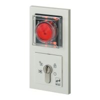
The escape door and key switch
module is installed in standard
flush-mounted switch boxes.
Install standard flush-
mounted boxes according to
requirements.
A low safety voltage between +12V -15% and +24V +15% must be sup-
plied to operate the device in accordance with DIN 60 950. You should
ideally use Power Supply Unit Type 1003FT-24-05, which is suitable for
use with a standard switch box (see separate fitting and installation
instructions). The required power supply can then be fed directly from
this unit.
Regulations
Preparatory
tasks
Providing
power supply