Concealed Vertical Rod Exit Device
7220
Installation Instructions
4
80-9472-0020-000 10/23
1-800-438-1951 • www.assaabloy.com
Copyright © 1999, 2013, 2023, ASSA ABLOY Access and Egress Hardware Group, Inc. All rights reserved. Reproduction in whole
or in part without the express written permission of ASSA ABLOY Access and Egress Hardware Group, Inc. is prohibited.
3. Size Device
Device must be fi eld cut to size
unless the standard opening
and the device are 36" (0.91m)
or 48" (1.22m).
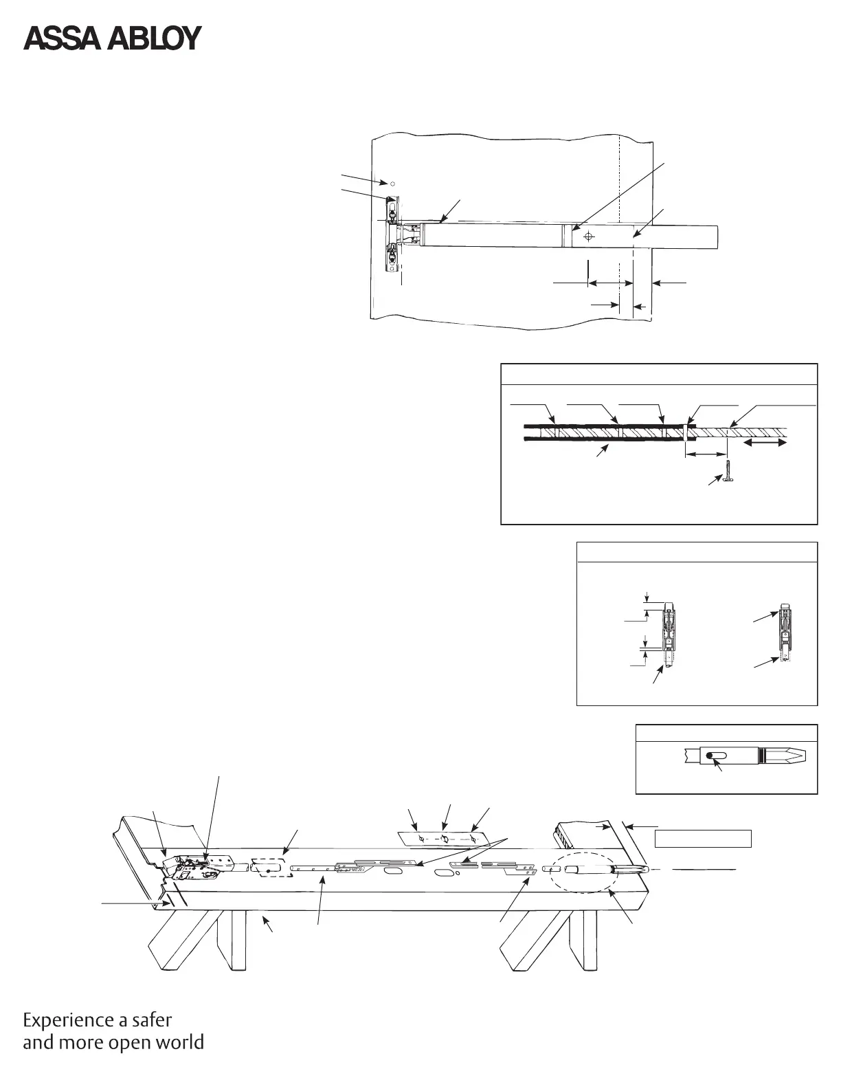
4. Rod Assembly & Preliminary Adjustment
A. Remove the door from the opening. Set fl at, device side up. (Do
not hang the door until Section 8 of device installation sheet.)
B. Set length of Top Rod Assembly (see Detail 1).
C. Connect Top & Bottom Rods to Arm/Bracket Assemblies. (2 Cotter
Pins each)
D. Align Rod Setup Gauge over Device Cutouts and Centerlines.
Tape Gauge to door face.
E. Connect Top Latch to Rod Assembly.
F. Set Top Latch and Rod Assembly in place on the door. Maintain
7/8"(21) location from top as shown.
G. Align Yoke Pin holes in Arm and Bracket Assembly with Alignment
Hole in Rod Setup Gauge. Adjust top Latch and Rod Assembly for
proper alignment. Latchbolt must be extended. (See Detail 2).
H. Thread bottom bolt into Bottom Rod Assembly. Set Bottom Bolt
Rod Assembly in place on door. Align Yoke pin hole in the Bottom
Arm and Bracket Assembly with Alignment Hole in Rod Setup
Gauge. Adjust Bottom Bolt until it protrudes 3/8"(10) + the gap
from Section 1, past the bottom edge of door. Make sure the
Bottom Bolt is fully extended, (See Detail 3).
Detail 3
Bolt fully extended
(Pin toward center of door)
Detail 2 - Top Latch
3/4
(19)
Latchbolt Extended
(Correct Assembly)
Latchbolt Retracted
(Incorrect Assembly)
Bolt Flush
to Chassis
Mounting
Bracket
(Removed)
Top Rod
(4) Free
Threads
(Typ. Ref.)
Detail 1 - Top Rod Assembly
8'
(2.44M)
7'6"
(2.29M)
7'2"
(2.18M)
7'
(2.13M)
6'8" (20.3M)
(Field Drill)
Adjust
Top Rod
4"
(102)
Cotter Pin
Tube
* For other door opening heights, locate and drill 1/8(3) dia. hole in top
rod( The Top Tube can be used as a drill guide for this operation).
3/8
(10)
LHR Door (Door Open)
Inside Face
Hinge Edge
of Door
Verify that there is no gap
between End Cover and Touch
Bar, prior to marking cutoff.
Mark cutoff line. Cut square
on line.
2-1/4
(57)
1-3/8
(35)
Minimum to Stile Edge:
Minimum:
Dogging
Hole
C
L
Align horizontal line on door
with edge of device
Align mounting
holes in door
with mounting
holes in device
E - Detail 2
G
B - Detail 1
H - Detail 3
G
D
H
C
C
A
F
H
7/8
(22)
Hold
G, H
* From Step 1
Gap* + 3/8 (10)
Adjust as required for
correct Rod length.
Device Mounting
Holes and Rods
Yoke Pin
Holes
C
L
Rod Setup Gauge
See page 10