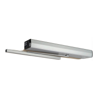
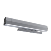
The Norton 5700 Series Power Operator is a sophisticated device designed to automate the opening and closing of pedestrian swing doors, enhancing accessibility and convenience in various indoor settings. This operator is engineered to conform to ADA (Americans with Disabilities Act) regulations and ANSI A156.19 standards for power assist and low energy power operated doors, making it suitable for environments requiring easy access for individuals with physical disabilities. The unit is non-handed, simplifying installation and reducing inventory requirements.
Function Description:
The core function of the 5700 Series Power Operator is to provide controlled, automated movement for swing doors. It can be configured for either "Power Assist Door" (PAS) or "Low Energy Power Operated Door" (POR) functions, meeting different operational requirements. The operator utilizes a motor assembly, an inverter, and a door closer mechanism to achieve smooth and reliable door motion. When activated, the motor drives a chain connected to a pinion extension/clutch assembly, which in turn moves the door through a slide arm or connecting link assembly, depending on the mounting type.
The operator incorporates a sophisticated control system that allows for precise adjustments of various parameters. It features open/close positioning magnets and a reed switch to accurately determine the door's position, ensuring consistent and safe operation. The inverter manages motor speed and torque, contributing to the smooth acceleration and deceleration of the door. A circuit breaker is included to protect the motor assembly and inverter from electrical overloads.
For safety, the operator includes an obstruction detection sensor, which can be adjusted to respond to impediments during door movement. It also allows for adjustment of the motor delay on opening, hold open time, motor torque at hold open position, and opening/closing speeds. These adjustable features enable customization to suit specific door types, traffic patterns, and safety requirements.
The unit can be integrated with various activation inputs, such as wall switches, card readers, or key switches, providing flexibility in how the door is triggered to open. For enhanced convenience, an optional RF receiver can be incorporated, allowing for wireless activation via remote transmitters.
Usage Features:
The 5700 Series Power Operator is designed for indoor use with pedestrian swing doors. It supports a maximum door size of 48 inches (1219mm) wide and 250 lbs (113.4kg). The installation process can be configured for either hinge (pull) side mounting or stop (push) side mounting, offering versatility to adapt to different door frame designs.
The operator's non-handed design simplifies the selection and installation process, as the same unit can be used for both left-hand and right-hand doors. It is compatible with doors hung on butt hinges (up to 5" max. width) or 3/4" offset pivots, with separate templates provided for other hinge conditions.
The unit offers both concealed and surface wiring options, allowing for a clean aesthetic or easier installation depending on the building's infrastructure. For concealed wiring, conduit fittings are integrated into the backplate, while surface wiring utilizes an optional bracket.
The control system allows for fine-tuning of door opening and closing speeds, backcheck, and latch speed. Backcheck provides hydraulic resistance during the door's opening cycle, preventing damage from forceful opening. Latch speed controls the final closing phase, ensuring the door latches securely without slamming. The hold open time is also adjustable, allowing the door to remain open for a specified duration after activation.
For fire and smoke barrier door assemblies, the operator is UL listed, provided the 120VAC power input is supplied through normally closed alarm contacts of a compatible UL Listed alarm system or alarm panel. This integration ensures that the door operates safely in emergency situations.
Maintenance Features:
Maintenance of the Norton 5700 Series Power Operator is designed to be straightforward, with clear instructions for adjustments and troubleshooting. Regular maintenance ensures optimal performance and longevity of the device.
Key maintenance aspects include:
- Power Disconnection: Always disconnect the main power to the operator prior to servicing or cleaning to ensure safety.
- Hydraulic Adjustments: The hydraulic valves for sweep speed, latch speed, and backcheck can be adjusted using a 1/8" hex wrench. These adjustments are crucial for maintaining proper door closing speeds and preventing damage.
- Power Adjustment: The door closing power can be adjusted using a 1/8" allen wrench, allowing for customization based on door weight and desired closing force.
- Position Magnet Adjustment: The open and closed position magnets, along with the reed switch, can be adjusted to ensure accurate door positioning and consistent operation.
- Troubleshooting Guide: The manual provides a comprehensive troubleshooting guide that lists common faults, possible reasons, and remedies/explanations. This helps in quickly diagnosing and resolving issues such as the door not opening, the motor not starting, or the door not closing.
- Dedicated Power Circuit: The operator requires a dedicated 120VAC power circuit from the main circuit breaker panel, which helps in isolating potential electrical issues and simplifies troubleshooting.
- Component Replacement: The modular design of the operator, with components like the motor assembly, inverter, and door closer, suggests that individual parts can be replaced if necessary, extending the lifespan of the unit.
By adhering to the installation and maintenance guidelines, the Norton 5700 Series Power Operator provides a reliable, accessible, and safe solution for automated pedestrian swing doors.