EasyManua.ls Logo

Assa Abloy Norton 6011 Series User Manual

Assa Abloy Norton 6011 Series
26 pages
To Next Page IconTo Next Page
Page #1 background imageLoading...
Page #1 background image
Copyright © 2019, ASSA ABLOY Accessories and Door Controls Group, Inc. All rights reserved. Reproduction in whole or
in part without the express written permission of ASSA ABLOY Accessories and Door Controls Group, Inc. is prohibited.
80-9360-1026-020 Rev 4 11/19
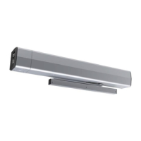
6011/6051 Series (Pull Side) Power Operator
Installation Instructions
Pour la version francaise voir www.nortondoorcontrols.com.
READ AND FOLLOW ALL INSTRUCTIONS. SAVE THESE INSTRUCTIONS.
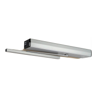
6051 Pull Side (Handed) 1/8" to 3" (3mm to 76mm) reveal
All components above with 7250-1(R or L)
instead of 7210-1A arm
This product can expose you to lead which is known to the state of
California to cause cancer and birth defects or other reproductive harm.
For more information go to www.P65warnings.ca.gov.
WARNING
Tools Needed
6011 Pull Side Max 1/8" (3mm) reveal
1/4-20
#7
#2 and #3
10" or 12"
3/8
Punch
Set (Inch)
Supplied Fasteners
Union Assembly
(6001U)
Union Spacer
(6001US)
Cover
(6001COV)
Arm Assembly
(7210-1A)
End Cap - RH
(6001ENRH)
Closer Assembly
(7500LAP)
Operator LAP
(6011LAP)
Conduit Assembly
(6001CON)
Backplate (6001BP)
Power Module Sub-assembly
(6001PM)
Power Supply
(6000SUP)
Motor (not eld
replaceable)
Track Assembly
(7200-1T)
Inverter
(6000IN)
End Cap - LH
(6001ENLH)
Double Egress Arm
(7250-1R/7250-1L shown)

Questions and Answers:

Assa Abloy Norton 6011 Series Specifications

General IconGeneral
Spring ForceAdjustable
BackcheckAdjustable
Series6011
MountingSurface Mount
ApplicationCommercial
ComplianceANSI/BHMA A156.4
Valve AdjustmentsYes
Door WidthUp to 48"
Closing PowerAdjustable
Temperature Range-20°F to 120°F

Summary

General Information

Operation Modes

Details the three operational variations of the low energy operator.

Opening Cycle Description

Explains how the door opens, stops for obstruction, and reopens.

Closing Cycle Description

Describes the door's closing process, including slowing and obstruction handling.

Infinite Hold Open Feature

Details the optional feature to keep the door held open indefinitely.

Before You Begin

Dimensions and Reinforcing Requirements

Specifies dimensions and recommended frame reinforcing for installation.

Mounting Hardware and Fasteners

Lists required mounting hardware and frame fasteners for different materials.

Technical Data Specifications

Provides key technical specifications like power, door width, and opening angles.

Prepare Frame and Door

Frame Preparation Steps

Details marking and drilling holes for mounting the backplate and conduit.

Frame and Door Preparation Steps

Mount Backplate

Instructions for sliding and aligning the backplate over mounting screws.

Prepare Door for Track Installation

Steps to locate and drill holes in the door for the track assembly.

Install Operator

Secure Backplate to Frame

Securing the backplate to the frame using specified screws.

Install End Caps

Attaching end caps to each end of the backplate using screws.

Operator Installation - LAP and Conduit

Install Operator LAP

Steps for installing the Operator LAP onto the mounted backplate.

Install Conduit Assembly and Wire to Building

Guides on orienting, securing, and wiring the conduit assembly.

Operator Installation - Modules and Assemblies

Install Power Module Sub-assembly

Securing the power module sub-assembly and connecting its wiring.

Connect Operator LAP and Power Module

Connecting the operator LAP and power module using specified connectors.

Install Union Assembly and Union Spacer

Steps for installing the union assembly and snapping on the union spacer.

Install Track and Arm

Mount Track to Door

Mounting the track assembly to the door using screws and sex bolts.

Install Arm Assembly

Steps for installing the arm assembly onto the operator's pinion.

Adjustments

Adjust Mechanical Closer Features

Adjusting closer valves (Sweep, Latch, Backcheck) for proper door function.

Adjust Spring Force

How to adjust the spring force for opening and closing effort.

Power Operator Configuration

Set HOME Procedure for Door

Configuring the door's closed and fully open positions via the control unit.

Selector Mode Switch Operation

Setting the selector mode switch for activation or continuous hold open.

Attach Cover to Finalize Installation

Align and Secure Unit Cover

Steps to align cut-outs and securely snap the cover onto the backplate.

General Electrical Information

Power Inputs and Wire Size

Details on power input connections, wire size recommendations, and current draw.

Wiring Practices and Codes

Information on standard wiring practices, local codes, and fire/smoke barrier requirements.

Controller Error Codes

Error Code Descriptions and Solutions

Lists common error codes displayed by the controller and their meanings.

Controller Interface Description

Screen 1 Settings and Adjustments

Details for Screen 1 settings like Mount, Hold Open, Open Delay, and Latch Retract.

Screen 2 Settings and Adjustments

Details for Screen 2 settings like Door Feedback, PDET Option, and various relay functions.

Wiring Diagrams

Standard Function Wiring

Diagram for standard door operation with switches.

Fail Secure Electric Strike Wiring

Wiring diagram for a fail-secure electric strike.

Wiring Diagrams - Strike and Exit Devices

Fail Safe Electric Strike/Electromagnetic Lock Wiring

Wiring for fail-safe electric strike or electromagnetic lock.

24VDC Electric Exit Device Wiring

Wiring diagram for a 24VDC electric exit device.

Wiring Diagrams - Dogging and Executive

Electric Dogging Exit Device Wiring

Wiring for electric dogging exit devices with touch bar monitoring.

Hard Wired Executive Function Wiring

Wiring diagram for hard-wired executive function.

Wiring Diagrams - Latch Retraction and Smoke

Electric Latch Retraction Exit Device Wiring

Wiring for electric latch retraction exit devices.

Smoke Ventilation - Blow Open Function Wiring

Wiring for smoke ventilation with blow-open function.

Wiring Diagrams - RF and Vestibule

Radio Frequency Standard Function Wiring

Wiring diagram for standard operation using wireless switches.

Radio Frequency Executive Function Wiring

Wiring diagram for executive function using wireless switches.

Wiring Diagrams - Vestibule Function

Vestibule Function Wiring

Wiring for vestibule applications with inside and outside door switches.

433MHz Receiver User's Guide

Receiver DIP Switch Settings

Configuration of DIP switches for relay activation modes.

Hand-Held Transmitter Configuration

Steps for learning and programming transmitters to the receiver.

Receiver Troubleshooting

Common issues and solutions for the 433MHz receiver.

585 Presence Detector Wiring

Detector Functionality and Programming

Describes detector operation and how to activate its presence detection.

Door Mounted Presence Detector Wiring

Sensor Configuration and Operation

Details on configuring door-mounted sensors for opening and closing cycles.

Troubleshooting Guide

Door Operation Issues Troubleshooting

Solutions for problems like door closing too fast, slow, or not opening correctly.

Error Message Troubleshooting

Guidance for resolving controller error messages.

Cover and Mounting Issues Troubleshooting

Solutions for cover not snapping on or staying on properly.

Installation Template

Left Hand Door Shown Template

Template for left-hand pull side application, showing dimensions.

Related product manuals