Do you have a question about the Assa Abloy Norton 7200 Series and is the answer not in the manual?
Instructions for preparing the door frame for closer mounting.
Steps for mounting the closer body to the prepared frame.
Procedure for hanging the closer body and securing it to the frame.
Installing remaining mounting screws for the closer back plate.
Attaching the closer arm shoe to the door face.
Connecting the closer arm to the operator and securing it.
Setting the initial spring tension by positioning the arm.
Adjusting the closing force of the door closer.
Fine-tuning sweep, latch, backcheck, and hold open positions.
Details for connecting electrical components for various unit types.
Adjusting the cam to set the desired hold open angle.
Securing the cover to the closer unit using provided screws.
Instructions for preparing the door frame for track mount installation.
Steps for mounting the closer body to the prepared frame.
Hanging the closer body and securing it to the frame.
Installing remaining mounting screws for the closer back plate.
Mounting the closer arm to the pinion square.
Securing the closer arm to the slider assembly with provided hardware.
Installing the track onto the door frame or header.
Connecting the closer arm to the slider assembly in the track.
Adjusting the closing force for consistent door closure.
Fine-tuning sweep, latch, backcheck, and hold open ranges.
Details for connecting electrical components for various unit types.
Adjusting the cam to set the desired hold open angle.
Securing the cover to the closer unit using provided screws.
Instructions for surface mounting power input for non-detected units.
Wiring diagram for 120V AC power input connections.
Wiring diagram for 24V DC power input connections.
Instructions for surface mounting power input for smoke detector units.
Wiring diagram for 120V AC power input connections.
Wiring diagram for 24V AC/DC power input connections.
Instructions for surface mounting power input for RF receiver units.
Wiring diagram for 120V AC power input connections.
Wiring diagram for 24V AC/DC power input connections.
Configuration options for DIP switches on the RF receiver.
Steps for programming transmitters using a handheld device.
Instructions for configuring push plates with the RF transmitter.
Procedure for deleting transmitter codes from the receiver.
Common issues and solutions for RF unit operation.
Diagrams illustrating the components of MPSO and MPDO closer units.
List and diagrams of parts included for pull side or double egress installations.
List and diagrams of parts included for push side installations.
Specifications and drill sizes for fasteners used in door closer installation.
List of product certifications for safety and compliance.
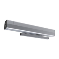
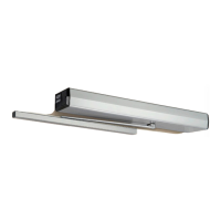
The Norton 7200 Series Multi-Point Hold Open is a door closer designed for both pull-side and push-side applications, offering controlled door operation with a hold-open feature. It is suitable for various door types and environments, providing adjustable closing force, speed, and backcheck.
The 7200 Series operates as a hydraulic door closer with an integrated hold-open mechanism. For pull-side applications, it utilizes a slide track, while push-side applications employ double lever arms. The device controls the door's opening and closing cycles, preventing it from slamming shut and allowing it to be held open at a desired angle.
The closer incorporates several adjustable controls to fine-tune its performance:
The device can be integrated with various electrical connections, including non-detectored, detectored, and RF remote receiver units, allowing for automated or remote control of the hold-open function.
The 7200 Series is designed for ease of installation and versatile application:
The 7200 Series is designed with maintenance considerations to ensure long-term reliability:
| Series | 7200 Series |
|---|---|
| Mounting | Surface |
| Size | Varies by model |
| Handing | Non-handed |
| Compliance | UL Listed |
| Armature Plate Material | Steel |
| Mounting Options | Surface |