Concealed Vertical Rod Exit Device
7220
Installation Instructions
6
80-9472-0020-000 10/23
1-800-438-1951 • www.assaabloy.com
Copyright © 1999, 2013, 2023, ASSA ABLOY Access and Egress Hardware Group, Inc. All rights reserved. Reproduction in whole
or in part without the express written permission of ASSA ABLOY Access and Egress Hardware Group, Inc. is prohibited.
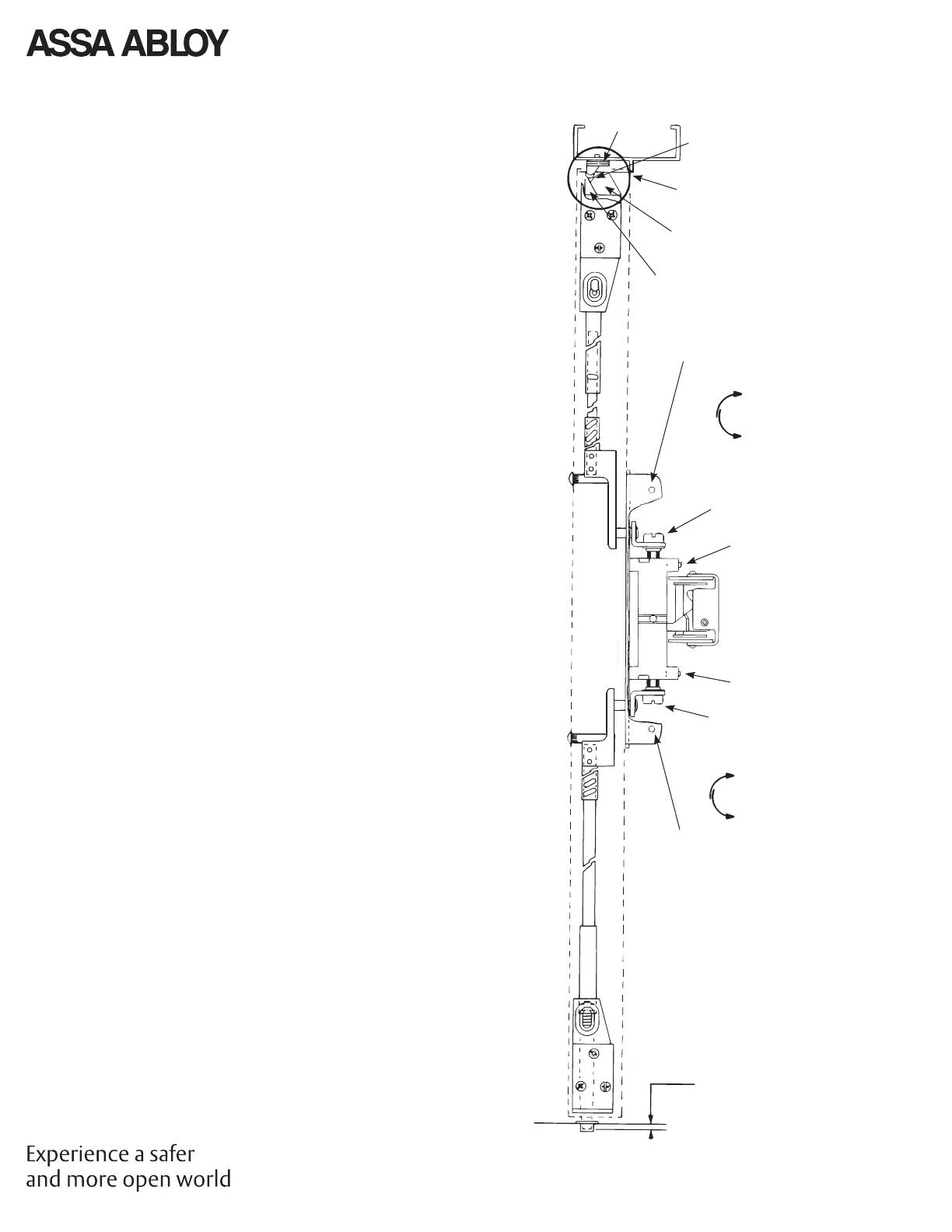
8. Complete the Installation
A. Rehang the door plumb and true to the opening. Set the
strike roller between the tripping lever and the bolt. DO
NOT PRELOAD THE BOLT. Shim the strike as needed.
Note: Rods should move freely inside the door. Bolts extend
automatically and should deadlock when the door closes
and the top strike hits the tripping lever. The top bolt should
retract fl at. The bottom bolt should travel 1/2" and engage
3/8" into the strike in the down position, without dragging
on the fl oor surface in the up position.
Test the device action by touchbar, by trim, and by
dogging. Adjust as needed.
B. Rod Adjustment for Proper Bolt Throw
1. Use a 3/32" hex wrench to loosen set screws B1 and B2.
2. Adjust the top rod fi rst with adjusting screw C1. With
the device in dogged position (panic devices) or the
touchbar fully depressed (fi re devices), adjust the top
rod so that the top latchbolt is fl ush and the hold back
feature is engaged. Lengthen the top rod an additional
1/2 turn for proper latchbolt positioning.
Note: If the adjusting screws bottom out before proper
device operation, the door and device must be removed
so larger adjustments may be made by threading the
rod in or out, or by moving the cotter pin to adifferent
hole in the rod (See "4. Rod Assembly & Preliminary
Adjustment" on page 4).
3. Adjust the bottom rod with adjusting screw C2. With
the top latch retracted in hold back position, and the
touchbar dogged or fully depressed, adjust the bottom
rod so that the deadbolt clears the strike by 1/16". The
bottom rod should be in position in the active case with
the square head of the connector hanging in the guide.
(See note in Step 2 above).
4. Check device operation by opening and closing the
door. An additional minor adjustment may be required
for full retraction and correct strike engagement.
Note: To avoid thread damage and provide positive
locking, be sure the set screws engage the fl ats on the
adjusting screws.
C. After acceptable device function, install third screw in top
strike to lock the strike in position with 10-24 x 3/4" PFHMS.
D. Install device cover and end cap with (2) 8-32 PFHMS each.
3/8
(10)
Cover Screw
Hole
Cover Screw
Hole
Tripping Lever
Bolt
Strike Roller
Shim
C2
B2
B1
C1
A
Bolt
Engagement
Longer
Bottom Rod
Shorter
Top Adjusting Screw
Bottom Adjusting Screw
Longer
Top Rod
Shorter