80-9472-0020-000 10/23
1-800-438-1951 • www.assaabloy.com
Copyright © 1999, 2013, 2023, ASSA ABLOY Access and Egress Hardware Group, Inc. All rights reserved. Reproduction in whole
or in part without the express written permission of ASSA ABLOY Access and Egress Hardware Group, Inc. is prohibited.
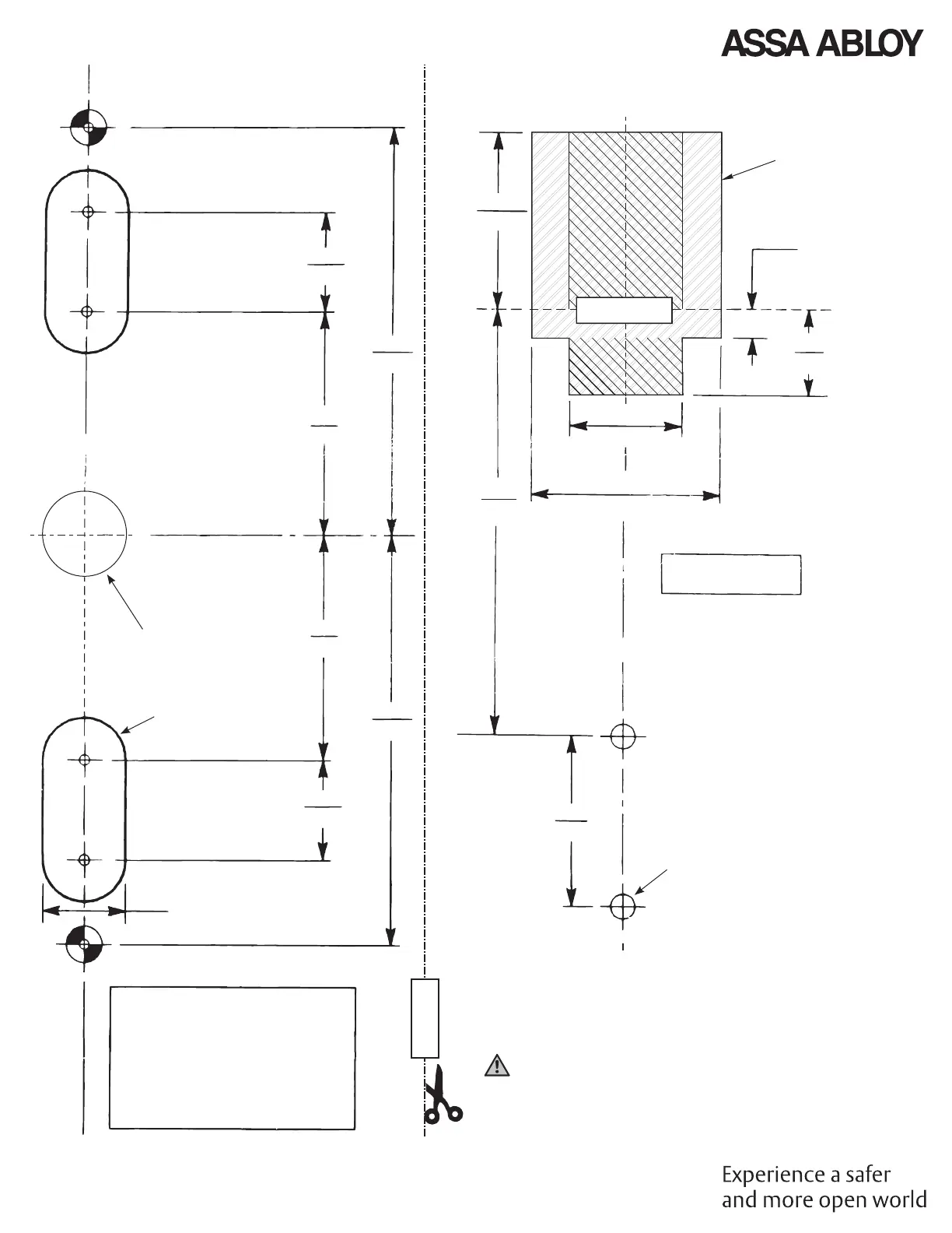
FOLD LINE
FOLD OVER TOP
EDGE OF DOOR
Door
Cutout
1/4
(6)
3/4
(19)
1
(25)
1-11/16
(43)
3-3/4
(95)
3/4
(19)
C
L
Device Mounting
Holes, Rods, and
Strikes
1-1/2
(38)
3-5/8
(92)
3-5/8
(92)
7/8
(22)
2
(51)
2
(51)
7/8
(22)
1-9/16
(40)
Thru This Face
(2 slots)
C
L
C
L
Device Mounting
Holes, Rods, and Strikes
Centerline
Horizontal Reference
and Device
A
A
TAPE TO DOOR
(INSIDE FACE)
TAPE TO DOOR
DEVICE
3/4 (19) Dia x
1/4 (6) Dia
Radius (Typical)
(2) Holes A:
1/4-20 tap
(metal reinforced doors),
or
3/8 (9.5) dia thru door for SNB
(all other doors)
CUT LINE
7/32 (5 50) Dia
Inside Door Face
Notes:
Unreinforced frames require that 10-24 blind rivet nuts (by others) be used to
bolt strike. Frames are considered not reinforced when strike mounting screws
cannot engage (3) full threads.
Dimensions are given in inches (mm).
Caution: Offi ce copiers and facsimile machines may change the size of a
drawing and make the template inaccurate to use as a door marker. If this is not
the original template packed with the device, use only the dimensions written
on the template to locate the holes on the door (do not use the template as a
door marker).
TOP LATCH CASE