Do you have a question about the Assa Abloy Besam SP33-M and is the answer not in the manual?
Highlights operational risks, injury, and electric shock hazards associated with product use and maintenance.
Lists environmental factors like fog, exhaust, or reflective surfaces that hinder sensor performance and require avoidance.
Defines the sensor's detection width and depth at a specific height, noting factors affecting actual range.
Visual guide for sensor placement relative to door width and leading edge for optimal performance.
Details on model, mounting height, power, operating conditions, response times, and configuration options.
Table providing specific detection area widths based on door width and sensor module configuration.
Steps for preparing and affixing the sensor profile to the door, including drilling and wiring considerations.
Guidance on correctly inserting sensor modules into the profile, noting Tx orientation and clip usage.
Detailed instructions for connecting power, sensor modules, and test inputs to the door controller.
Procedures for initializing the sensor modules and performing learning cycles using the function switch.
Instructions for adjusting the sensor module angle to optimize detection range and safety.
Configuration guide for dipswitches A and B to set detection zones, frequency, immunity, and output functions.
Steps for verifying sensor functionality, LED indicators, and output signals after installation and configuration.
Essential information for end-users regarding cleaning, maintenance, and when to contact a service engineer.
Table listing common problems, their possible causes, and recommended countermeasures for sensor issues.
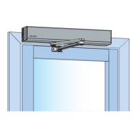
The Besam SP33-M is a non-contact switch designed for door mounting and use on automatic swing doors, ensuring safety and compliance with various standards such as DIN 18650 and EN ISO 13849-1. It is crucial to read the operation manual carefully to ensure proper operation and prevent serious injury or death. The device features LED indicators that provide visual feedback on its status and operation.
The SP33-M operates using triangulation to detect objects within its specified area. It can be configured with a minimum of one master module and one LED module, and a maximum of four sensor modules and two LED modules. The master module is equipped with Dipswitches A and B, while slave modules only have Dipswitch B. Dipswitch A on the master module connected to the door controller dictates the settings for all connected master and slave units.
The sensor's primary function is to establish a detection area that triggers door operation. This area can be adjusted in terms of width and depth angle. The "non-detection zone" is a crucial setting, defining the height from the floor where the sensor begins to detect. This zone can be configured using a combination of Dipswitch A1 and B1 settings. The device also includes a presence timer, which can be set via Dipswitch A4, determining how long the output remains active when an object is detected.
For installations on double swing doors, the frequency of each sensor must be set differently using Dipswitch A2 to prevent interference between modules. The device also features an immunity setting (Dipswitch A3) to prevent self-operation (ghosting), which may slightly reduce the actual detection area when activated.
A test input feature, controlled by Dipswitch A7, allows for testing the sensor's functionality, with an adjustable delay time set by Dipswitch A8. The sensor also incorporates a self-monitoring function, configurable via Dipswitch B3, which is important for safety and compliance. The mounting side (output select) can be set using Dipswitch B4, determining whether the sensor detects for the opening or closing side of the door and influencing the LED indicator's color.
The SP33-M is designed to be connected to a door system equipped with a SELV circuit, and the overcurrent protection of the power supply cable must be less than 2A. The device provides two presence impulses (Form C relay and Voltage output) for stop and reverse impulses, respectively, which are crucial for door control.
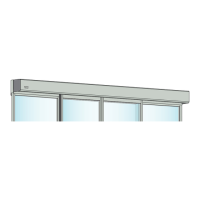
Installation of the SP33-M involves mounting the profile, inserting the sensor modules, and wiring the device to the door controller. The profile can be cut to match the door width and should be affixed leaving at least 20mm from the door edge for endcap attachment. Mounting holes need to be drilled for secure fixation. When mounting sensors on both sides of a door, a wiring hole is necessary to connect the sensor modules.
Sensor modules are inserted into the profile, ensuring the lens marked "Tx" is positioned towards the corresponding door edge. The modules can be rotated 180° if needed by detaching and reattaching the mounting clips. It is essential to fix the sensor modules firmly using the mounting clips.
After power is supplied or dipswitch settings are changed, an initialization process is required. This involves pushing the function switch on the master module for more than 2 seconds. The LED indicator will then blink red and green, followed by blinking green to indicate the number of connected sensor modules, and finally yellow and red, signaling completion of initialization.
Following initialization, a learning cycle must be performed by pushing the function switch for less than 2 seconds. During this cycle, the sensor learns the non-detection zone. It is critical to avoid entering the detection area while the sensor is learning. Once learning is complete, the sensor enters stand-by mode, indicated by a solid green LED.
The angle of each sensor module can be adjusted using the angle adjustment screw to ensure the door stops before contacting an obstacle. After any angle adjustments, a new learning cycle must be initiated.
The device's LED indicators provide clear status feedback: solid green for stand-by, solid red for opening side detection, solid orange for closing side detection, and various blinking patterns for initialization, learning, saturation, sensor failure, or communication errors.
To ensure proper functioning and longevity of the SP33-M, several maintenance features and guidelines are provided. The front cover should always be kept clean. If dirty, it should be wiped with a damp cloth; harsh cleaners or solvents should not be used. The sensor should not be washed with water.
Users are explicitly warned against disassembling, rebuilding, or repairing the sensor themselves, as this could lead to electric shock or device breakdown. In case of a fast red blinking LED indicator without any object in the detection area, or for any changes in settings, the installer or service engineer should be contacted. The front cover should also not be painted.
After applying power, it is recommended to wait 10 seconds before performing a walk-test of the detection area to ensure proper operation. It is also important to avoid placing any objects that move or emit light (e.g., plants, illumination) in the detection area, as this can interfere with the sensor's performance.
Troubleshooting guidelines are provided for common issues. For instance, if the sensor has no function, checking the power supply voltage and wiring is recommended. Incomplete initialization or learning requires pushing the function switch for the appropriate duration. If the sensor operates by itself (ghosting), removing interfering objects, setting different frequencies for double swing doors, adjusting module positions or angles, or extending the non-detection zone are suggested. Waterdrops on the front cover can also cause ghosting and should be kept off.
If the sensor functions without the front cover but not with it, checking module angles, cleaning the front cover, or replacing a scratched front cover are recommended. If the door remains open or closed without an object, re-learning the non-detection zone, changing the presence timer setting, or adjusting module positions/angles are potential solutions. Communication errors require checking communication wires. A dirty front cover on the inner or outer side can also cause issues and should be cleaned. For sensor failure (fast red blinking), contacting the installer or service engineer is advised.
| Type | Automatic sliding door operator |
|---|---|
| Power Supply | 230 VAC, 50/60 Hz |
| Operating Temperature | -20°C to +50°C |
| Max Door Weight | 120 kg |
| Opening Speed | 0.7 m/s (adjustable) |
| Closing Speed | 0.7 m/s (adjustable) |
| Hold-open Time | Adjustable, 0-60 seconds |
| Noise Level | < 60 dB(A) |