Do you have a question about the Associated Electrics PRO4 SC10 and is the answer not in the manual?
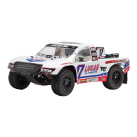
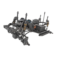
Details the key features of the Pro4 SC10 Ready-To-Run RC vehicle, including radio system, motor, and suspension.
Provides guidance on hardware identification, special symbols, and items needed for completion.
Lists various sizes and types of button head screws with 1:1 scale views for identification.
Lists various sizes and types of flat head screws with 1:1 scale views for identification.
Lists various sizes of ball bearings with 1:1 scale views for identification.
Lists set screws, nuts, and washers with 1:1 scale views for identification.
Provides essential steps and safety warnings for charging the vehicle's battery.
Detailed instructions on how to properly install the battery into the RC vehicle.
Important information and tips for handling and using LiPo batteries.
Guidance on setting up and tuning the radio transmitter and its controls.
Details the components for assembling the front and rear differentials.
Assembly instructions for the front and rear differential units.
Instructions for assembling the center differential, including spur gear.
Completes center differential assembly and begins shock absorber construction.
Detailed steps for assembling the shock absorbers.
Instructions for filling shock absorbers with fluid and bleeding air.
Finishes shock assembly and builds the servo saver mechanism.
Instructions for assembling the steering rack, bellcrank, and front suspension linkage.
Assembles the front gearbox, including outdrives and input pinion.
Attaches front arms and gearbox components to the chassis.
Installs body posts and mounts for the vehicle's body.
Assembles the steering blocks and caster blocks for the front suspension.
Assembles the front hubs with bearings and drive shafts.
Installs front suspension components and front anti-roll bar.
Completes the installation of the front anti-roll bar system.
Assembles the 15.50mm steering turnbuckles for the front suspension.
Assembles the 22.00mm steering turnbuckles for the front suspension.
Installs the motor mount and attaches it to the chassis.
Attaches the chassis guard to the main chassis.
Installs the front and rear drive shafts.
Assembles the rear gearbox components.
Assembles the rear arm mounts and associated components.
Installs the rear shock tower and body mount.
Assembles the rear hubs with bearings, pin, and hex.
Installs rear suspension components and rear anti-roll bar.
Completes the installation of the rear anti-roll bar system.
Assembles the 26.00mm rear camber turnbuckles.
Installs the skid plate and other front chassis components.
Attaches front suspension parts and shock guards.
Assembles the front bumper, bumper brace, and light buckets.
Installs the rear bumper, bumper brace, and mud flaps.
Attaches rear bumper components and hook and loop straps.
Installs the battery tray foam, receiver box, and wire clip.
Installs the motor and pinion gear onto the motor mount plate.
Guidance on setting the correct gear mesh for optimal performance and durability.
Installs the spur gear cover and connects the servo.
Assembles the servo link turnbuckle.
Installs the receiver, ESC, and antenna tube.
Instructions for mounting tires to the wheels using CA glue.
Installs the assembled wheels onto the vehicle.
Attaches the pre-painted SC body and body clips.
General advice for new users to ensure consistent driving and setup adjustments.
Guidance on how to properly set the gear mesh for optimal performance.
Explanation of camber angles and their effect on handling.
Instructions on adjusting camber links for roll and steering response.
Explanation of Ackermann effect and how to adjust steering geometry.
Lists optional upgrade parts available for the vehicle.
Catalog of various silicone shock fluids with different weights.
Catalog of various silicone differential fluids with different viscosities.
Information on optional high-performance electronics.
| Brand | Associated Electrics |
|---|---|
| Model | PRO4 SC10 |
| Category | Motorized Toy Car |
| Language | English |