16
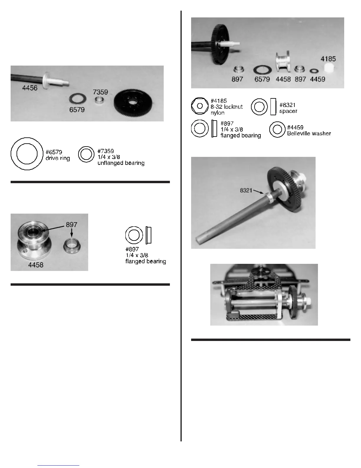
To make the assembly easier, stand the axle on end so
that the threaded end is facing up (we have laid the parts down
to make the photo easier to shoot). Now take one of the #6579
drive rings, put a thin coat of diff lube on it and slip it over the end
of the axle. Center it on the diff hub. Next slide on the #7359 ball
bearing. This is followed by the #4460 spur gear and diff balls
we assembled in fig. 48.
Fig. 49
❑ Fig. 50 Take the two remaining #897 ¼” x 3/8” flanged
ball bearings and install one into each side of the #4458 diff hub
spacer.
Fig. 50
❑ Figs. 51, 52 & 53 Now install the second #6579
drive ring. This is followed by the #4458 diff hub spacer (with
bearings). Each side of the diff hub spacer is flanged. On one
flange there are two threaded holes. This will be the wheel side.
Slide the diff hub spacer on so the unthreaded side goes on first.
Now center this hub onto the #6579 drive ring.
Look at the #4459 Belleville washer. Slide this washer
over the threaded end of the axle with the raised outer edge
facing out. This will put the load on the inner race of the outer
#897 ball bearing. Finally, thread on the #4185 8-32 nylon
locknut and snug it down. Fig. 51 shows the #4458 without the
#897 bearings from fig. 50 installed. We will adjust the diff at the
end of the assembly manual. Go ahead and set aside the four
#3656 ball bearings that remain in the bearing bag. We will not
need them until later in the manual.
Go back to bag #5 and remove the #8321 aluminum
rear axle spacer (fig. 52). One side of the axle spacer has a
raised lip. Slide the axle spacer over the graphite portion of the
axle with the raised lip facing away from the diff assembly. Now
take the axle assembly and install it into the rear pod assembly
from the right or passenger side. Slide the axle through the
bearing in the right motor plate and then out through the bearing
in the left bulkhead.
Fig. 51
Fig. 52
Fig. 53
❑ Figs. 54 & 55 Remove the #4540 left wheel hub and
the #4436 4-40 x 5/16” socket set screw (bag #5). Thread the
set screw into the left wheel hub. Look at the wheel hub. You will
see that one side has a larger raised circular area and the other
is a smaller circular area that is beveled on the outer edge. Now
slide the wheel hub onto the left side of the rear axle. We want
the smaller circular side to go on first. Seat the hub against the
bearing and tighten the set screw. Do not force the hub against
the bearing; we want to have a couple of thousandths of end
play on the axle. The only screws remaining in bag #5 will be the
four #6932 4-40 x 5/16” SHCScrews that are for mounting the
rear wheels. Set these aside; we will use them later.