17
Fig. 54
Fig. 55
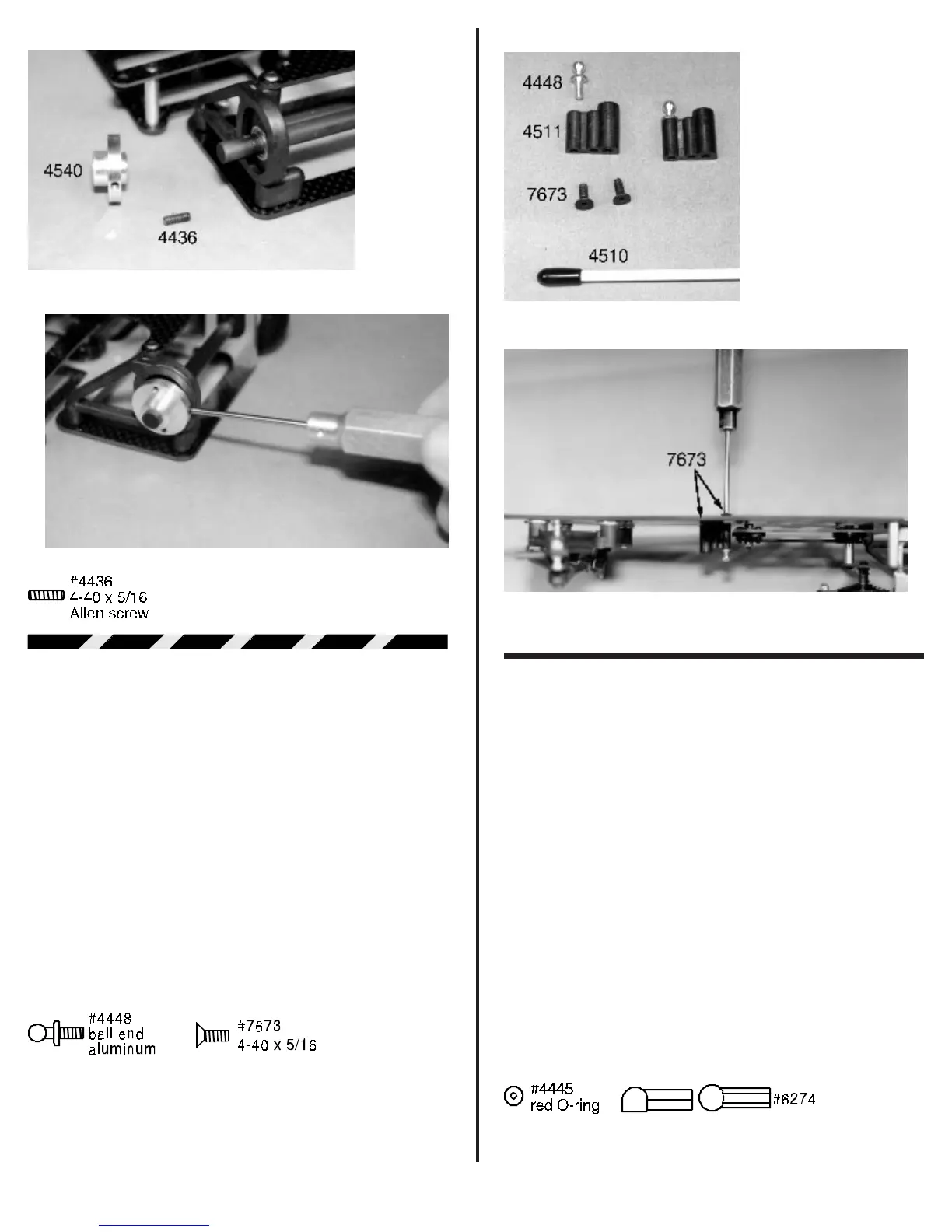
SHOCK ASSEMBLY
❑ Figs. 56 & 57 Open bag #6, the shock bag, and
remove the #4511 molded front shock/antenna mount, one
#4448 aluminum ball end, and two #7673 4-40 x 5/16”
FHSScrews. Look closely at the #4511 shock/antenna mount.
One side is flat. This will be the bottom of the mount. Now look
at the top. One side is larger than the other. Thread the #4448
aluminum ball end into the small side. Now go to the master bag
and remove the #4510 fiberglass antenna rod. The plastic end
cap will already be installed. Push the exposed end of the
antenna rod into the hole in the large side of the shock/antenna
mount.
In front of the T-bar you will see the two mounting holes
for the shock/antenna mount. Use the two #7673 4-40 screws
from the bottom of the chassis to secure the mount to the
chassis.
Fig. 56
Fig. 57
❑ Figs. 58, 59 & 60 Now we can begin assembly
of the Delta shock.
Note: Associated does not have individual
replacement parts for the Delta shock, unless you see an
Associated part number indicated in the photos and written
instructions.
We will start by removing the #4445 small red O-
ring, the Delta shock piston/shaft assembly and the small brass
washer. Slide the #4445 O-ring onto the piston/shaft assembly
followed by the brass washer. Push them down against the
shock piston. Next remove the Delta aluminum shock body, the
black nylon spring adjusting collar and one #6274 plastic ball
end cup from bag #6. Thread the black nylon spring adjusting
collar onto the shock body. Make sure the hex portion is away
from the large end of the shock body. Thread it on just enough
for all the threads on the adjusting collar to be on the shock
body. Now thread the #6274 plastic ball end cup onto the small
threaded nipple of the shock body. Again thread it down to the
end of the threads.
From the same bag remove the black plastic shock end
cap and the shock internal spring. Look at the plastic shock end
cap. If your cap has any flashing on the side away from the
threads it must be trimmed off flush as shown in fig. 60. Now
insert the internal spring into the end of the plastic end cap.