25
RADIO RECEIVER INSTALLA-
TION
We are now ready to begin the installation of the radio
receiver. If you have not already chosen your radio system,
Associated recommends staying with a top name brand radio
system. Names like Airtronics, Futaba, JRpropo, or KOpropo
are the most recognized brands available. Depending upon the
type and size of components plus the number of cells you are
using, your best layout may be different from the one shown in
the manual.
❑ Figs. 88, 89 & 90 In the master kit bag you will
find a 1 ½” x 6” strip of double stick tape (servo tape). For our
installation we show installing the receiver behind the servo on
the right (passenger side) of the chassis. If you have a smaller
receiver you may be able to install the receiver flat on the
chassis. If you have a standard receiver you can mount it on its
edge as shown.
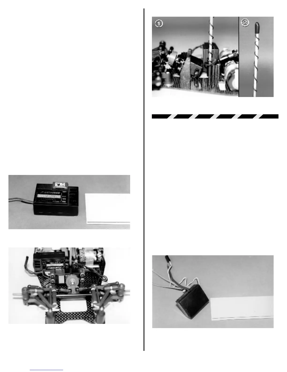
Cut a piece of the servo tape to match which ever side
of the receiver you want be secure to the chassis. Now take the
antenna wire and coil it around the #4510 fiberglass antenna
rod. When you reach the top of the antenna rod, remove the
plastic end cap put the end of the wire over the top of the tube
and then press the end cap back over the wire and rod. Fig. 89
& 90 shows the receiver installed on the chassis and the wire
wrapped on the antenna rod with the plastic end cap installed.
Fig. 88
Fig. 89
Fig. 90
ELECTRONIC SPEED
CONTROL INSTALLATION
We can now begin to install the electronic speed
control (ESC). Again we recommend using name brand speed
controls. We consider the top brands to be LRP, Novak, and
Tekin. If you stay with a high quality manufacturer like these you
should not have any problems.
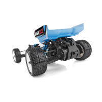
❑ Figs. 91, 92 & 93 Now cut another piece of servo
tape to match the bottom of the speed control case. Attach the
ESC to the chassis with the servo tape. Fig. 92 shows the
proper location for our installation.
Now take the servo wire from the steering servo and
plug it into channel #1 (rudd) of the receiver. Next take the servo
wires from the ESC and plug it into channel 2 ("thro") of the
receiver see fig. 92. You will find a small bag in the master kit
bag which contains four #7709 4" electrical wire ties. You can
use these to bundle the servo wires to clean up the wiring
installation. Fig. 93 shows the servo wires bundled and secured
with the wire ties.
Fig. 91