Do you have a question about the Associated Research OMNIA II 8257 and is the answer not in the manual?
Outlines the manufacturer's warranty, its terms, and conditions for coverage.
Explains product marking and caution/warning symbols used in the manual for user safety.
Defines terms and acronyms used throughout the manual for clarity and understanding.
Provides essential safety precautions for operating the instrument, covering general safety and user service.
Details the main features and capabilities of the OMNIA II instrument, highlighting key functionalities.
Guides the user through unpacking the instrument and inspecting it for any shipping damage.
Covers the installation process, including work area, power, and basic connections for the instrument.
Details requirements for setting up a safe and functional test station, including location and work area.
Specifies the electrical power requirements, voltage, and frequency necessary for the instrument's operation.
Details the fundamental connections required to set up the instrument, focusing on the power cable.
Outlines the recommended operating and storage environmental conditions, including temperature, humidity, and altitude.
Provides detailed functional specifications for the OMNIA II, covering input, dielectric withstand, and ground continuity.
Explains how to operate the instrument, detailing front and rear panel controls.
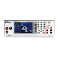
Describes the function and location of each control and indicator on the front panel of the instrument.
Explains the purpose and location of controls and connectors found on the rear panel of the instrument.
Details specific rear panel controls and connectors relevant to the 82x6 and 82x7 models.
Describes the initial power-on sequence and the default main menu screen displayed by the instrument.
Guides the user through accessing and configuring system settings, including time, date, and security.
Explains the function of various keys used for navigating and interacting with the setup system screens.
Details how to set the instrument's date and time, including format options.
Explains the calibration alert feature that notifies the user when calibration is due.
Describes hardware settings and options, such as Smart GFI, Continuity Scanner, and PLC Remote.
Details the security features, including enabling/disabling security and user setup for access levels.
Explains how to configure user interface settings like alarm volume, language, and color style.
Describes how to configure the instrument's power-on behavior, including animation and home screen selection.
Provides access to test programming functions, including adding, editing, and deleting test steps.
Explains how to add new test steps to a sequence, selecting from various test types.
Details how to edit existing test steps within a sequence, modifying their parameters.
Describes the process of deleting a test step from a sequence and confirming the action.
Explains how to insert text prompts into test steps for user guidance during execution.
Covers file handling operations, including creating, saving, loading, and deleting test files.
Explains the Fail Stop function, which halts a test sequence upon detecting a failure.
Details the parameters used for configuring tests, including their definitions and default values.
Defines various test parameters used in configuring tests, such as Voltage, Current limits, and Timers.
Lists the default parameters for different test types, allowing quick setup or reset.
Guides the user through the process of setting up a new test sequence step by step.
Details the parameters and settings for configuring an AC Withstand test.
Explains how to set up and configure the parameters for a DC Withstand test.
Guides the user through setting up the Insulation Resistance test, including parameter configuration.
Describes the Continuity and Ground Bond tests and their setup procedures.
Details the parameters and settings for configuring an AC Ground Bond test.
Explains how to configure the parameters for a DC Continuity test.
Details the setup for the Functional Run Test, including parameters for models 82x6 and 82x7.
Guides the user through setting up the Leakage Current test, including parameters for models 82x6 and 82x7.
Explains how to connect test leads and adapter boxes to the instrument for various tests.
Details the adapter box connections for DUTs, specifically for OMNIA models 8204, 8206, and 8207.
Describes the interlock connector and its role in enabling/disabling instrument output for safety.
Explains the DUT input voltage connections for models 82x6 and 82x7, emphasizing single-phase supply.
Details the scanner connections and their operational specifications, including channel configurations.
Provides access to the main screen for executing tests and viewing results.
Explains how to load previously saved test files into the instrument for execution.
Describes the Single Step function, allowing tests to be run one step at a time for debugging or analysis.
Details the Fail Stop function, which controls whether a test sequence stops or continues after a failure.
Explains how to review test results, including measurements and pass/fail status.
Guides the user through the process of executing a selected test or test sequence.
Describes the metering screens and displayed parameters for different test types performed by the OMNIA II.
Explains the various messages displayed on the instrument, including test status and error messages.
Lists and explains test status messages that appear during and after test execution.
Provides a list and explanation of error messages that may appear on the instrument for all models.
Details the remote signal outputs used for monitoring PASS, FAIL, and PROCESSING conditions via relays.
Explains remote control functions and access to pre-programmed test files via remote connectors.
Describes the use and configuration of the USB/RS-232 interface for instrument control and data transfer.
Provides cabling configuration details for the RS-232 interface using a 9-pin serial port.
Specifies the required COM port configuration settings for USB/RS-232 communication.
Explains how to send commands to and receive data from the instrument via the USB/RS-232 interface.
Details the optional GPIB interface, its capabilities, and conformity to IEEE-488.2 standards.
Describes the standard GPIB connector and connection configurations.
Explains how to set and manage the GPIB address for device communication.
Lists the interface functions that define a device's communication capabilities over a bus.
Provides a comprehensive list of commands for controlling the instrument via USB, RS-232, and GPIB.
Discusses echo and response handling for USB/RS-232 and GPIB communication.
Lists commands used to control test execution, output voltage, and current remotely.
Details commands for creating, modifying, and managing test setup files remotely.
Explains commands for editing test parameters remotely and querying their values.
Details commands for editing system parameters remotely and querying their values.
Lists query commands used to retrieve test data, results, and hardware status remotely.
Explains IEEE 488.2 common commands required for bus communication and control.
Describes the status reporting system, including event and summary registers for monitoring instrument conditions.
Explains the GPIB service request capability and how it is enabled using the Status Byte Enable register.
Covers how the instrument saves and deletes parameters in non-volatile memory using specific commands.
Lists and describes the available factory-installed options, including their codes and functionalities.
Outlines the FailCHEK menu, providing access to verification processes for instrument failure detectors.
Details the procedure for verifying the continuity test function and its expected results.
Explains the process for verifying the Ground Bond test function and interpreting its outcomes.
Describes the procedure for verifying the AC Hipot test function and its expected results.
Details the process for verifying the DC Hipot test function and its expected outcomes.
Explains the steps for verifying the Insulation Resistance (IR) test function and its results.
Outlines the warranty requirements, including conditions for extended coverage and annual recertification.
Covers the hardware calibration procedure for specific LCT ranges, especially after board replacement.
Explains how to initialize the calibration mode on the OMNIA II by pressing a button during power-on.
Describes how to navigate and select specific calibration points within the instrument's calibration menu.
Lists each calibration point and the required loads, standards, and processes to perform accurate calibration.
Specifies settings for touch current limits, including AC, DC, and peak measurements.
Details auto-ranging display specifications for touch current measurements, covering various ranges and accuracies.
Provides specifications for touch current display in fixed ranges, detailing accuracy across different levels.
Details auto-ranging display specifications for touch voltage measurements, covering various ranges and accuracies.
Provides specifications for touch voltage display in fixed ranges, detailing accuracy across different levels.
Details auto-ranging display specifications for touch voltage measurements (AC+DC), covering various ranges and accuracies.
Provides specifications for touch voltage display (AC+DC) in fixed ranges, detailing accuracy across different levels.
Details auto-ranging display specifications for touch voltage (Peak) measurements, covering various ranges and accuracies.
Provides specifications for touch voltage display (Peak) in fixed ranges, detailing accuracy across different levels.
| Brand | Associated Research |
|---|---|
| Model | OMNIA II 8257 |
| Category | Measuring Instruments |
| Language | English |