20
Installation, operation and maintenance manual; Level Control System
- Do not handle the unit with damp or wet hands.
- The unit may only be handled by authorised personnel or qualified service engineers.
Do not allow unauthorised personnel or unqualified service engineers to handle it.
2 INSTALLATION AND ASSEMBLY
NOTE:
- Read the whole of the manual carefully before installing the unit.
- On receiving the unit, check that it is in a good state of repair.
- Identify all components prior to their installation.
2.1 FASTENING AND LEVELLING THE SENSOR
Components required for fastening the unit:
Fastening required depending on the installation 2
DIN 9021 D6 A4 flat washer 4
DIN 934 M6 A4 nut 4
11) Fasten the anchor bolts (②
②②
②
c) to the fountain wall.
WARNING: Risk of damage to the unit. Level the unit so that the fountain’s highest water
level does not rise above position n4 and the lowest level does not fall below rod n1 (see
Fig. 1). The purpose of the slots found above position n4 is to allow the air in and out of the
inside of the sensor and to prevent the build-up of air pockets.
WARNING: Risk of damage to the unit. Protect the unit from power surges by connecting an
earth wire (③
③③
③) to one of the joints between the anchor bolt and nut (②
②②
②).
12) Fasten and level the unit at each of its fastening points ②
②②
② using:
• A set of nuts and washers (②
②②
②a) on the front.
• A set of nuts and washers (②
②②
②
b) on the back.
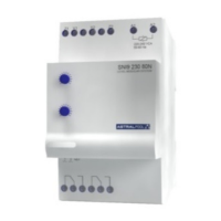
2.2 FASTENING THE CONTROL UNIT
WARNING: Risk of damage to the unit. Fasten the control unit out of the fountain. The
control unit has an IP-20 protection rating.
The control unit has a DIN rail for mounting it on a control panel.