Fountain units
Installation, operation and maintenance manual; Level Control System 21
2.3 WIRING
WARNING: Risk of damage to the unit. Check that all IP68 connectors are properly sealed
and that they prevent water from getting through. Electrical components may become
damaged by flooding and the unit could lose its warranty.
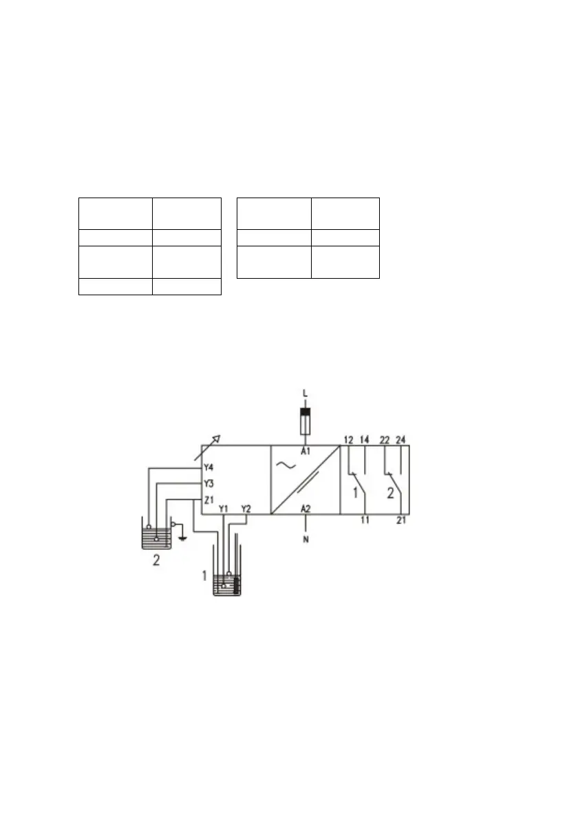
13) Connect the sleeve of sensor’s wiring (①
①①
①) to the inlets on the control unit:
wire
UC inlet
wire
Black Z1 Blue Y3
Grey Y1
Green and
yellow
Y4
Brown Y2
14) Connect the control unit’s relays to the power supply’s control system.
e) Relay 1: contacts NA, NC and common (r1).
f) Relay 2: contacts NA, NC and common (r2).
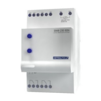
15) Connect the control unit’s power intake (Fig. 2; L, N) to the mains power supply (230 V
AC).
3 OPERATION AND MAINTENANCE
3.1 ON/OFF SWITCH
The level control system starts working when the control unit is switched on from the
fountain’s control system (connections L and N).