Installation & Servicing Instructions ATAG Q-Series
35
13.2 Checking the O
2
The O
2
percentage is set by the factory. It has to be checked during inspection,
maintenance and faults.
This can be checked by means of the following procedure:
- Remove the black cover of the gas valve.
- Put the boiler into operation and take care that it can deliver its heat;
- Press the MODE-key for 5 seconds.
- The diplay will show COdE followed by an arbitrary number;
- Select by means of the + or the - key the code C123;
- Press the Store-key to conrm the code (code blinks 1 x);
- Press the MODE-key until SERV is shown;
- Press the STEP-key once until 1 is shown;
alternately 1 and OFF will be shown.
- Calibrate the O
2
meter ;
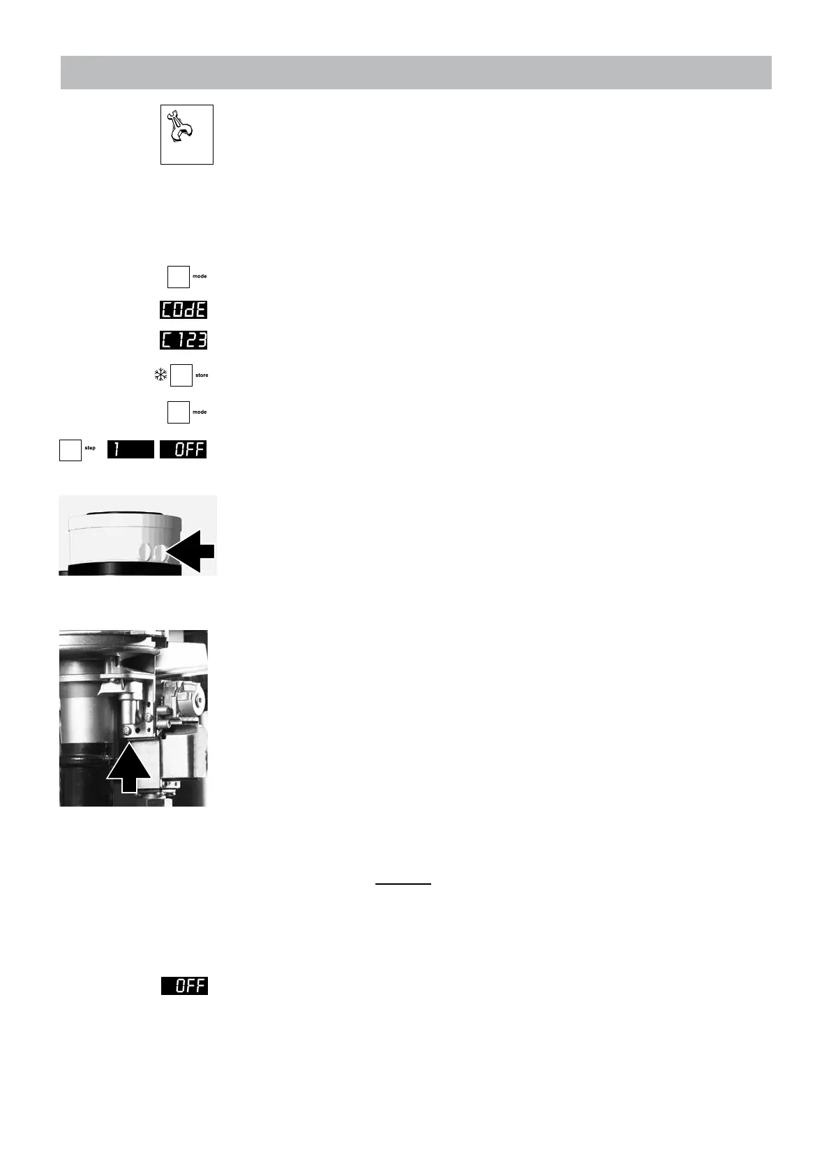
- Place the lance of the O
2
meter into the check point (see g. 13.2.a);
- Press the + key until the maximum value (in kW) is achieved;
The boiler will burn on full load (value on display in kW)
Natural gas Propane
- O
2
percentage at full load = 4,7% (+/-0,2%) 5,1% (+/-0,2%)
- CO/CO
2
ratio less than 0.004%
- Let the O
2
meter do its measuring procedure.
- Adjust, if necessary, the adjustment screw to correct the O
2
value
(see g. 13.2.b).
Finally, the O
2
percentage at low load must be checked:
- Press on the - button until the minimum value has been reached.
The boiler will be burning at low capacity.
- Leave measuring O
2
to the measuring equipment and check if the measured
O
2
percentage on low load is between following values:
Natural gas Propane
- O
2
percentage at low load between 5,0% and 7,0% 5,1% and 7,0%
- CO/CO
2
ratio less than 0.004%
Contact ATAG Heating when the measured values is outside this range.
Ending the O
2
measuring procedure:
- Press the - key until OFF is shown (keep key pressed).
With this the procedure has ended.
- Replace the black cover on the gas valve and x it with the screw.
adjustment screw
figure 13.2.b
Measuring point
figure 13.2.a
 Loading...