Installation & Servicing Instructions ATAG Q-Series
38
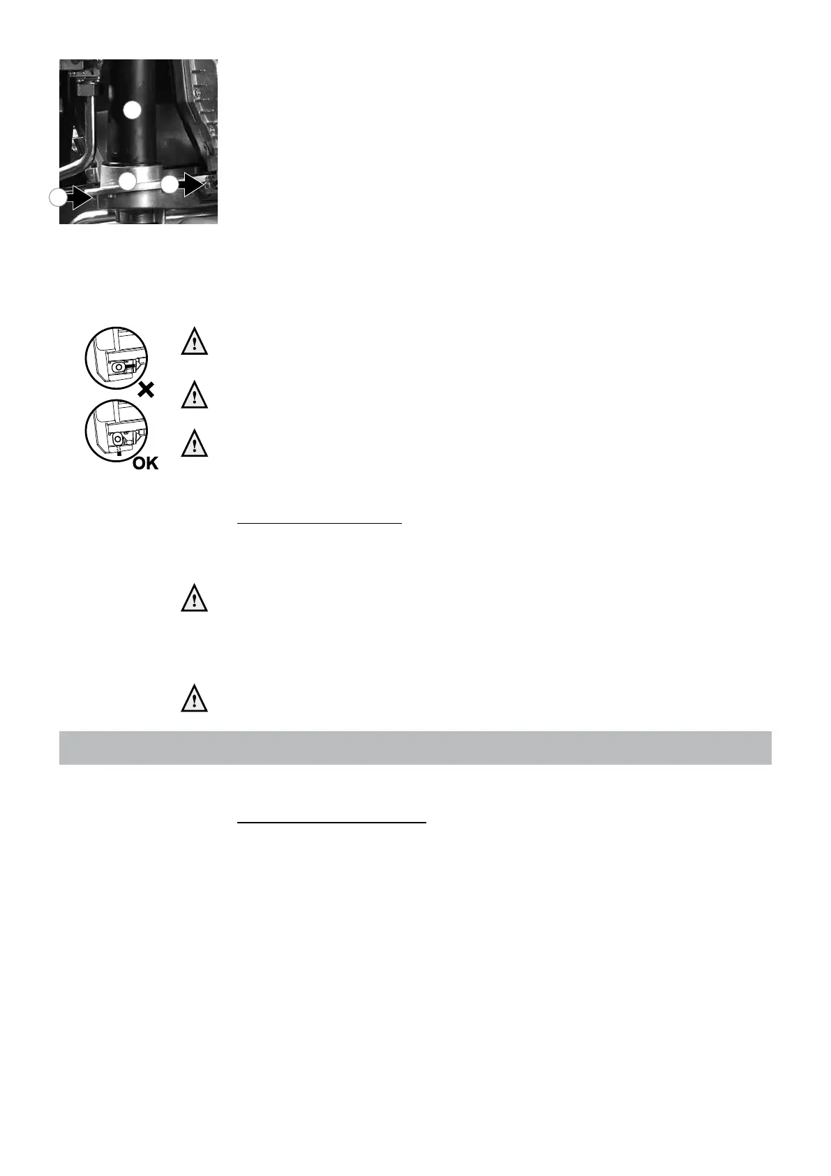
Step 2: Condensate tray
- Remove the plug from the ue gas sensor if present;
- Turn the two short clamping rods (11 and 12) ¼ turn with the hex key and remove
them by pulling them forward; Note the correct turning direction (red indicator,
g. 13.3.k);
- Lift the exhaust pipe (13) out of the condensate tray (14);
- Press the condensate tray (14) carefully downwards and remove it by pulling it forward;
- Replace the gasket between condensate tray and heat exchanger by a new one;
- Clean the condensate tray with water and a hard brush;
- Check the condensate tray on leaks.
Step 3: Retting is done in reverse order.
Note that all gaskets seals completely.
Pay attention that the gasket seals completely all around during reassembly of
the condensation reservoir.
During installation pay attention to the correct position of the clamp bars. These
have to be in a vertical position.
Always replace the gaskets of the removed parts during maintenance, if
required.
Put the boiler into operation and check the O
2
(see page 35).
Cylinder (when applicable)
Follow the complete service section of the cylinder commissioning checklist supplied
with the cylinder.
In the event that parts require replacement, use only genuine parts supplied by
ATAG Heating UK Ltd.
Please contact your installer or ATAG Heating UK Ltd. for further details. Contact details
can be found on the back page of this manual.
After servicing, complete the relevant Service Interval Record section of the
Benchmark Checklist located on the inside back page of the document.
13.4 Draining the installation
During servicing one of the following items has to be drained:
Central heating system - boiler
The central heating system and boiler can be drained using the ll- and drain valve
installed in the system. If service valves are installed (advised) the boiler can be
drained seperately from the rest of the installation via the drain valves on the service
valves.
Condensate tray gure 13.3.k
11
12
13
14
gure 13.3.l
 Loading...