Installation & Servicing Instructions ATAG Q-Series
7
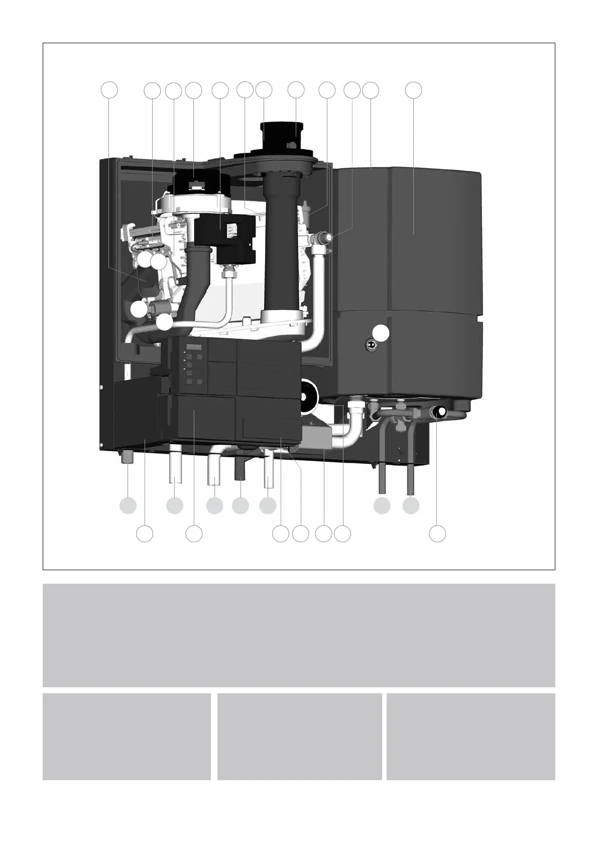
1 heat exchanger
2 ignition unit
3 fan unit
4 air inlet damper
5 gas valve
6 safety valve
7 automatic air vent
8 ceramic burner cassette
9 cylinder DHW (Combi)
10 operating panel
11 Control Tower (CMS)
12 water lter return CH
13 three-way valve
14 circulation pump (A-label)
15 thermostatic mixing valve
16 ue gas discharge
T1 ow sensor
T1a secondary ow sensor (Q60S)
T2 return sensor
T3 cylinder sensor DHW (combi)
P1 water pressure sensor
ATAG Q gure 4.a
4 2 1 3 175 16 7 6 918
C
E
13 14 15
W
G
19 10
T1
8
11
T2
T3
P1
KRA
17 combustion air supply
18 air box
19 type plate
G gas pipe
A ow connection central heating
R return connection central heating
C condensation / safety discharge
pipe
E expansion vessel pipe (Q25S,
Q38C and Q51C)
K cold water pipe (combi)
W hot water pipe (combi)
12
T1a

 Loading...