•
/'
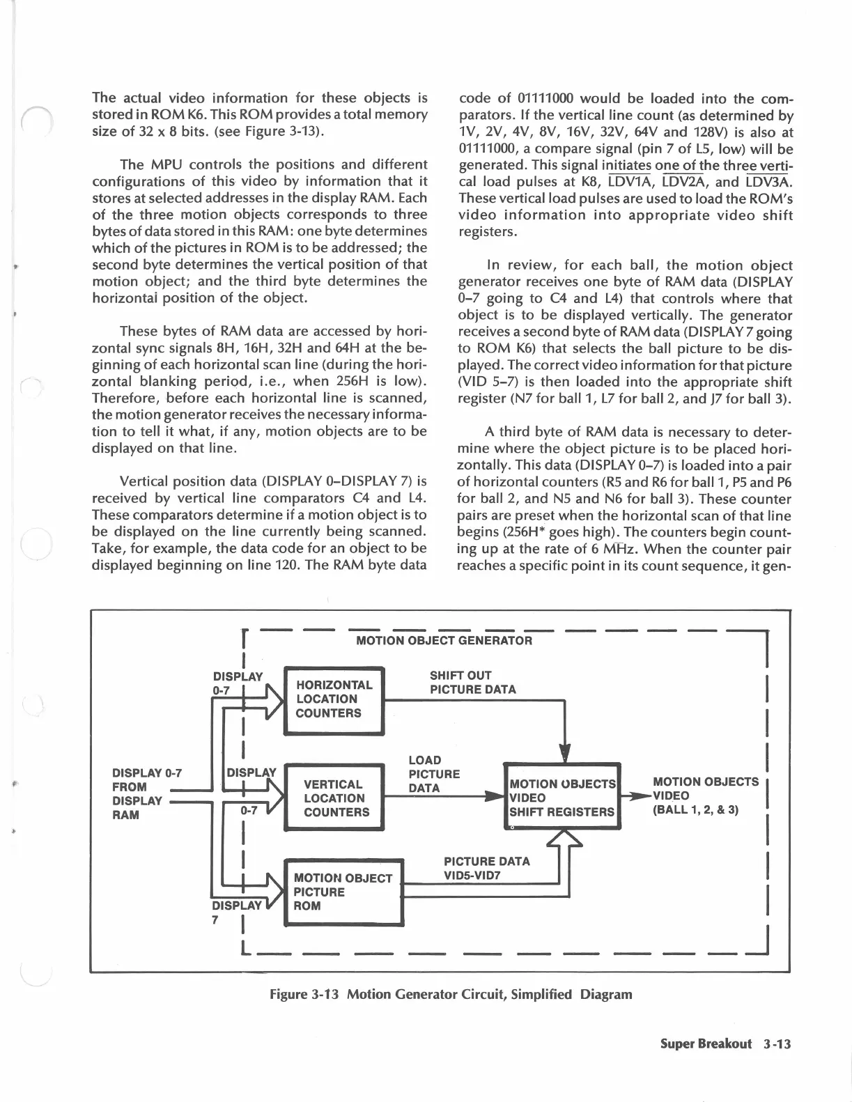
The actual
video
information
for
these
objects
is
stored
in
ROM
K6.
This
ROM
provides
a
total
memory
size
of
32
x 8 bits. (see Figure 3-13).
The
MPU
controls
the
positions
and
different
configurations
of
this
·
video
by
information
that
it
stores at selected addresses
in
the
display
RAM.
Each
of
the
three
motion
objects
corresponds
to
three
bytes
of
data
stored
in
this
RAM:
one
byte
determines
which
of
the
pidures
in
ROM
is
to
be addressed;
the
second
byte
determines
the
vertical
position
of
that
motion
object;
and
the
third
byte
determines
the
horizontal
position
of
the
object.
These bytes
of
RAM data are accessed
by
hori-
zontal
sync signals
8H,
16H, 32H and 64H at
the
be-
ginning
of
each
horizontal
scan
line
(during
the
hori-
zontal
blanking
periqd,
i.e.,
when
2S6H
is
low).
Therefore,
before
each
horizontal
line
is scanned,
the
motion
generator
receives
the
necessary
informa-
tion
to
tell
it
what,
if
any,
motion
objects
are
to
be
displayed
on
that
line.
Vertical
position
data (DISPLAY 0-DISPLA Y
7)
is
received
by
vertical
line
comparators
C4
and
L4.
These
comparators
determine
if
a
motion
object
is
to
be displayed
on
the
line
currently
being
scanned.
Take,
for
example,
the
data
code
for
an
object
to
be
displayed
beginning
on
line
120. The RAM
byte
data
code
of
01111000
would
be
loaded
into
the
com-
parators.
If
the
vertical
line
count
(as
determined
by
1V, 2V, 4V, 8V, 16V, 32V, 64V and 128V) is also at
01111000, a
compare
signal (pin 7
of
LS,
low)
will
be
generated. This
signal initiates
one
of
the
three
verti-
cal load pulses at
KB,
LDV1A, LDV2A, and LDV3A.
These vertical
load pulses are used
to
load
the
ROM's
video
information
into
appropriate
video
shift
registers.
In
review,
for
each
ball,
the
motion
object
generator
receives
one
byte
of
RAM data (DISPLAY
0-7
going
to
C4
and
L4)
that
controls
where
that
object
is
to
be displayed vertically. The
generator
receives a second
byte
of
RAM data (DISPLAY 7
going
to
ROM
K6)
that
selects
the
ball
picture
to
be dis-
played. The
correct
video
information
for
that
picture
(VID S-7)
is
then
loaded
into
the
appropriate
shift
register (N7
for
ball 1,
L7
for
ball 2, and
J7
for
ball 3).
A
third
byte
of
RAM data is necessary
to
deter-
mine
where
the
object
picture
is
to
be placed
hori-
zontally.
This data (DISPLAY 0-7)
is
loaded
into
a
pair
of
horizontal
counters
(RS
and
R6
for
ball 1,
PS
and
P6
for
ball 2, and
NS
and N6
for
ball 3). These
counter
pairs are preset
when
the
horizontal
scan
of
that
line
begins (2S6H* goes
high).
The
counters
begin
count-
ing
up
at
the
rate
of
6
MHz.
When
the
counter
pair
reaches a specific
point
in
its
count
sequence,
it
gen-
r - -
MOT10N'OBJECT'GENE'RATo_R_
I
I
I
I
I
DISPLAY 0-7
FROM
DISPLAY
0-7
DISPLAY
---
---
RAM
0-7
DISPLAY
7 I
HORIZONTAL
LOCATION
COUNTERS
VERTICAL
LOCATION
COUNTERS
SHIFT OUT
PICTURE
DATA
LOAD
PrCTURE
DATA
PICTURE DATA
MOTIOt~
OBJECT
_____
v_1D_s_-v_1D_1
___
_
PICTURE
ROM
L
__
Figure 3-13 Motion
Generator
Circuit, Simplified Diagram
MOTION
OBJECTS
I
VID_EO
(BALL
1, 2, & 3)
I
I
I
_J
Super Breakout 3 -13