— 20 —
6. Trouble shooting
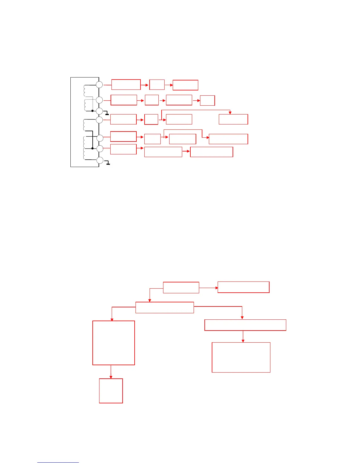
Complete set power supply outline
6.1 No raster, no picture, no sound
General, these failures are produced by power sources, because of which refer to a wider area, so
that can be divided them two conditions to explain: no +B 117 V and existing +B 117 V.
(1) No +B(117 V) voltage (voltage of network 110 V ac)
These failures may be caused by switching type power. Because of the TV set has no-load
protection, over-load protection, over-current protection, once these protections are activated, the CPU
will enter to “STAND BY” status. So that status confuses with conventional CPU standby, some
difficulties are occurred for failure estimation. When the switching type power supply operating
normally +B=117 V, but +B=17 V when come into standby status.
T611
26V
Rectifying and
Detection
H.Dri
Power Supply
117V
Rectifying and
Detection
H.OUT
Power Supply
15V
Rectifying and
Detection
Audio Power
Amplifying
14V
Rectifying and
Detection
10V
N603 / 12V
Rectifying and
Detection
CPU
Power Supply
N602 / 5V
N201
V. O U T
Power supply
Check fuse F601 or R602
Check voltage on D pole of V613
(switching transistor)
Check C601,
C603~C606, L601,
V613, V502 at
condition of
short-circuit?
Replace the
parts of
failure
Check 110 V ac input and
VD603~VD606 rectifying,
V613.
Y
N
=140V
Y
Check voltage+B
=0V
Refer to the no operation
failures of CPU
=17V