— 21 —
(2) Existing +B 117 V
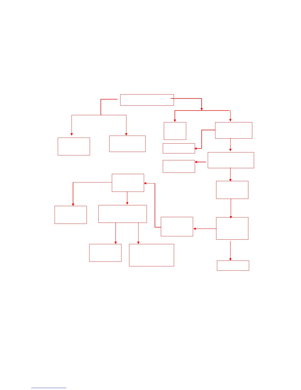
These failures may be caused by abnormal operation of horizontal scan circuit, to confirm which
can observe the filament of tube whether bright on. If determined horizontal scan in abnormal
operation, look for the failure start from the horizontal drive stage. Search upward to LA76814 with
method of checking dc voltage and waveform according to sequence: N201 PIN27/H.OUT port→
N201 PIN25 power supply→ N603/15 V output→ N101CPU/PIN42(STAND BY) output.
Check voltage at pin of V501(C)
=19 V
Check V505B pole
and N201/PIN27
waveform
Check V501
horizontal
drive stage
Check filament
circuit of FBT~CRT
Check horizontal
output stage and
deflection circuit
Check
corresponding parts
Check N201/PIN25=5V
(input current at this pin is
10 mA)
Check N201
Check voltage at
N101/PIN16=0 V
Check voltage at
V602E, V602C
After restart TV, check
voltage of negative pole of
VD2002 <10 V
Check CPU
according to non-
operation
Check
N101/CPU/PIN42
=5 V
Check CPU/PIN42
STANDBY status
Check voltage of main
power supply whether too
high or value of C
511
C
512
abnormal
Check VD2002
Check V604
N
Y
=26V
<18V
Y
N
Y
N
N
=2.3V
Y
N
N
10V
Y
Y