— 25 —
·Pin No.6: PWM output of volume control
·Pin No.7: NC
·Pin No.8: NC
·Pin No.9: GND
·Pin No.10 and 11: 32 kHz oscillator
·Pin No.12: VDD (5V)
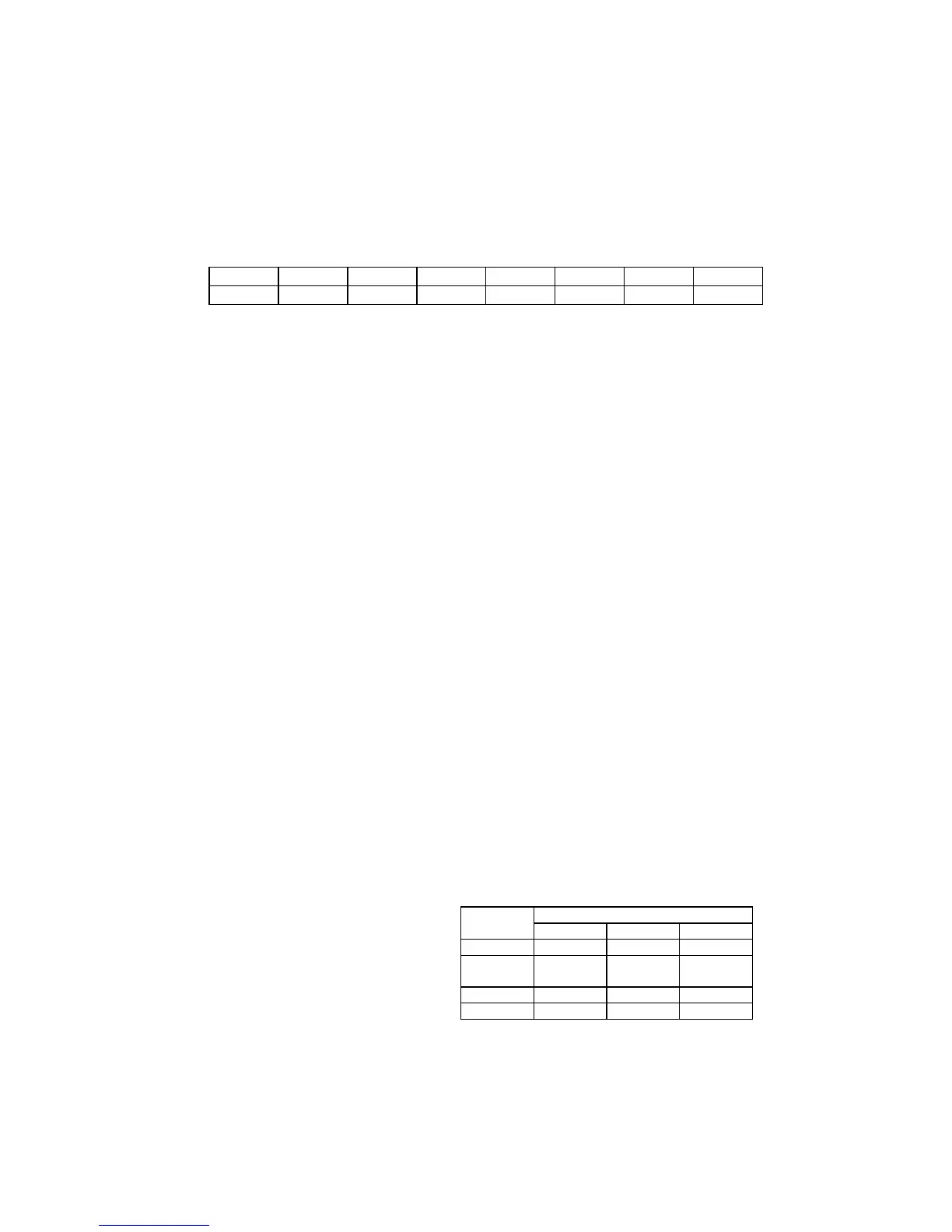
·Pin No.13: Key input
Function
MENU TV/AV POWER V+ V- P+ P-
Voltage
0 0.625 1.25 1.875 2.5 3.125 3.75
·Pin No.14: TEST function input
·Pin No.15: AFT voltage input
·Pin No.16: X-RAY protection input (valid for high level)
·Pin No.17: Reset (valid for high level)
·Pin No.18: filtering
·Pin No.19:Full TV signals input, used for CCD Sampling signal.
·Pin No.20: Vertical pulse input
·Pin No.21:Horizontal pulse input.
·Pin No.22, 23, 24: R, G, B screen display output
·Pin No.25: OSD blanking output
·Pin No.26: NC
·Pin No.27: I
2
C data bus (SDA0) port
·Pin No.28: I
2
C clock bus (SCL0) port
·
Pin No.29: SDA1 (no used)
·Pin No.30: SCL1 (no used)
·Pin No.31: NC
·
Pin No.32: NC
·Pin No.33: Identification signal input
Note: If no signal at TV mode, SD (PIN33) is at low level, after 10 seconds, CPU will enter
to status of standby. In other conditions (Video, S-Video), this status cannot occur.
·Pin No.34: Remote signal input
·Pin No.35 and 36: NC
·Pin No.37: NC
·Pin No.38: Blanking output as TV turn
off. Only when turn-off power switch, it
outputs high level.
·Pin No.39: Sound MUTE output. In
normal at low level, when switching channel
or in case of no signal, it outputs high level.
· Pin No.40 and 41: Control signal
output of TV/AV(AV1)/AV2/S-VHS etc.
·Pin No.42: STAND BY output. In
normal condition at high level, in STAND BY
status at low level.
MODE CPU PIN NO.
PIN40 PIN41 PIN2
TV H H H
AV H L H
•
AV 1
•
AV2 L H H
S-VHS L L L
TV/AV Truth-value table