SMART TDS BLOWDOWN CONTROLLER
3. TECHNICAL SPECIFICATIONS
Enclosure : IP 40 - EN 60529
Maximum ambient temperature
: 55 °C
Main supply voltage : 230 V +/– 10 %, 50/60 Hz
115 V +/– 10 %, 50/60 Hz (Opsiyonel)
Maximum power consumption : 3 VA
Output signal : 4-20 mA, Relay contacts
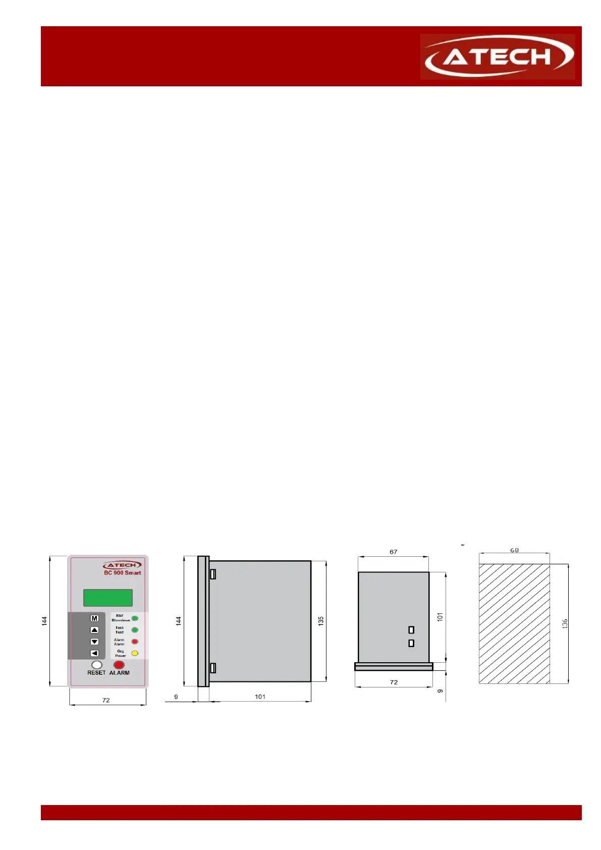
Indicators and adjustors : 1 yellow LED for indicating “Power”,
1 green LED for indicating “Blowdown”,
1 red LED for indicating “Test”,
1 red LED for indicating “Alarm”,
1 button “ALARM” for checking alarm,
1 button “RESET” for resetting the alarm,
4 pushbuttons for parameter settings.
Dimensions (height x depth x width)
: 144 x 110 x 72 mm
Installation, commissioning and maintenance of this device must be done by a qualified person in compliance
with the operating instructions.
4.1 Installation to panel
Smart Bottom Blowdown Controller BC 700 is front panel mounting enclosure type and can be applied to the front
panel with two screw clamps supplied.
Allow 20 mm minimum clearance all round the unit for air circulation.
Figure 3 Panel cut out dimensions of Smart Bottom Blowdown Controller BC 900
Please refer to "BCV 900 Installation and Operation Manual for Automatic TDS Blowdown Control Valve" and
"CP 920, CP 930 or CP 950 Installation and Operation Manual for Conductivity Probe" for detailed information