D620.388.00_QS_UK_01
13 / 42
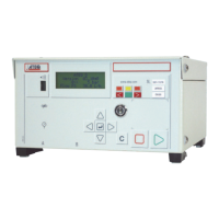
Ref Name Description
1
J1 Analog outputs - pressure and flow (option)
2
J5 Fieldbus connector
3
J8* Extender (not operational)
4
J10 Program selection extension connector (option)
5
J12 Printer RS232 connector / Modbus (option) or Profibus (option)
6
M1 External capillary option
7
J13 Temperature probe connector (option for external capillary)
8
P External back pressure connector (option)
9
- Input connector to the air filter (valves or regulator air supply)
10
- 0.6 MPa valves air supply input (1 MPa range) or vacuum input
11
TEST Capillary connector to connect to the part under test
12
- Regulator output (indirect mode or bypass option or external
capillary option)
13
- Pneumatic output for external bypass option
14
ATM Output capillary (indirect mode): has to be left to the atmosphere
15
B Pneumatic output for external shut off option or B automatic
connector option
16
ATM Output to be left to the atmosphere
17
A Pneumatic output for external dump option or A automatic
connector option
18
ATM Output to be left to the atmosphere
19
- Air supply energy information
20
ATEQ Part number / Serial number
21
M2 External capillary connector (option)
22 - Ground
23
J11 Relay board connector (digital inputs/outputs and 24VDC-2A
power supply)
24
J9 Outputs code board connector (digital inputs/outputs)
25
J7 Connector for 24VDC-2A or 100/240VAC power supply
(according option provided)
26
J4* USB (not operational)
27
J3* Dry contact input for ERD test mode (option)
28
J6 Fieldbus connector
29
J2* Network (not operational)
* These connectors are not operational. They are provided for future development of our
devices.