2221
4.4 Electrical installation
4.4.1 Input and output requirements
NOTICE
Caution, risk of danger
· There is a danger of electrical shock of high voltage in
inverter ’s operation; only electricians of professional skills can
operate.
·All connections with this equipment shall be done under non-
voltage state.
· The inverter may be damaged if input or output terminal is
incorrectly plugged.
Failure of acting upon this information may cause serious
1) Battery
The positive and negative highest voltage of the battery shall not exceed 1000V,
otherwise, the equipment will be in over-voltage protection state, and cannot work
normally. Recommended battery capacity is 50kWh
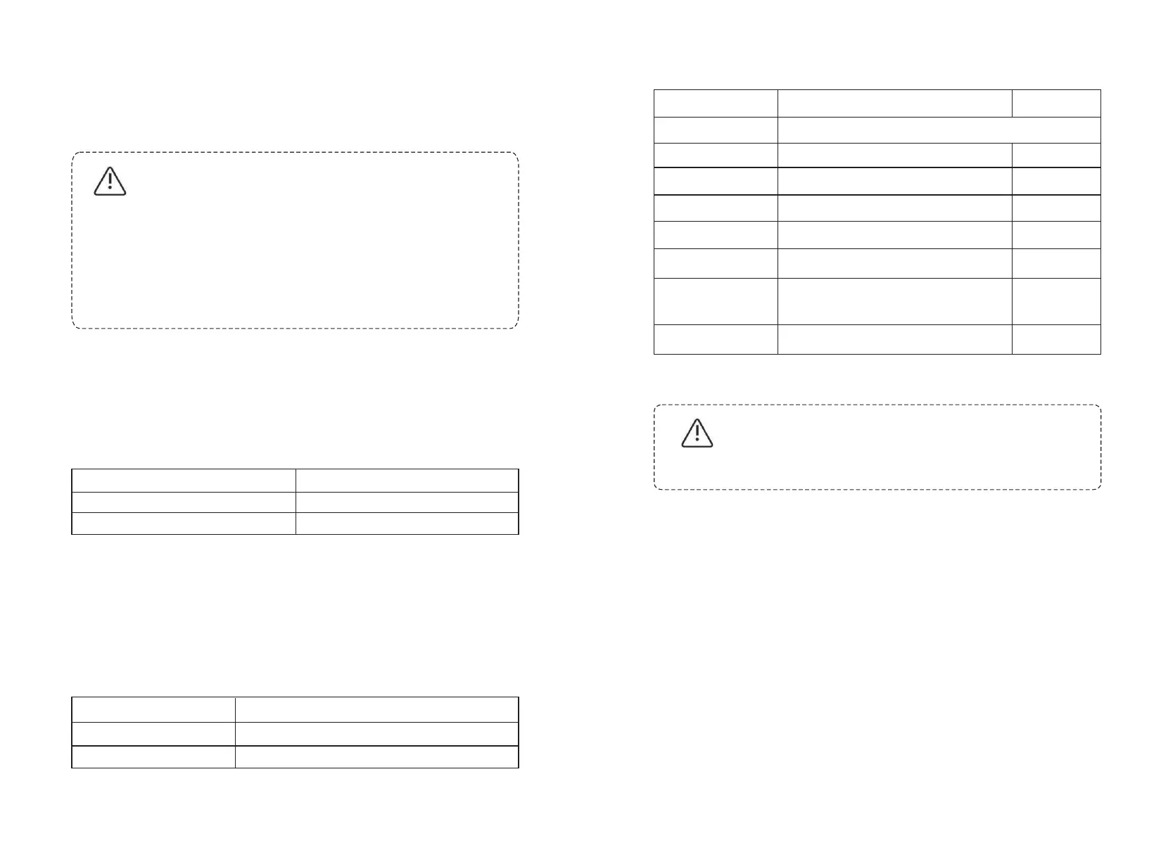
Model ATESS HPS50
Recommended battery capacity 50kW. h
Battery Voltage Limit 1000V
2) Three-phase grid
Inverter will continuously inspect whether the grid satisfy the grid connected
conditions. The following is the grid limit for satisfaction of local Grid connected
Conditions (requirements in different countries may vary, the value can be setup
and please refer to local grid connected regulations for details), and the grid is
three-phase grid. Meanwhile, it shall be permitted by local power supply
department before install Grid-connected inverted power.
Model ATESS HPS50
Grid Voltage Limit
Grid Frequency Limit
310Vac~450Vac
45Hz-55Hz/55Hz-65Hz
Cable (Cu) Cable Diameter Requirements (mm²)
Model
ATESS HPS30
3) Cable requirements
Aperture
PV and BAT
Φ8,20N*m
1 input cable with each 35 mm²
PV and BAT
1 input cable with each 35 mm²
Grid input A B C
2
1 input cables with each 50 mm
Communication Wire
0.75mm², shielded Twisted pair is recommended
/
Earth Wire
More than 16 mm².Green and yellow is
recommended
2
1 input cables with each 35 mm
2
1 input cables with each 50mm
Φ8,20N*m
Φ8,20N*m
Φ8,20N*m
Φ8,20N*m
Φ8,20N*m
Grid output A B C
N Wire
4.4.2 DC side wiring
CAUTION!
Caution, risk of danger
The positive and negative of the battery shall not be connected
in reverse. A multimeter shall be used to determine the polarity
first, and then connect into the corresponding input ends of the
Specific procedures are as follows:
1) Cut off the distribution circuit breaker at the DC side, and ensure that no
voltage on the wire at DC side.
2) Determine the positive and negative with a multimeter.
3) Connect the positive of the battery to the "Battery-input +"of The HPS50
4) Connect the negative of the battery to the "Battery-input +"of The HPS50
5) Connect the positive of the panels to the "PV-input+" of HPS50
6) Connect the negative of the panels to the "PV-input-" of HPS50
7) Please be sure that all wirings are fastened.