25 26
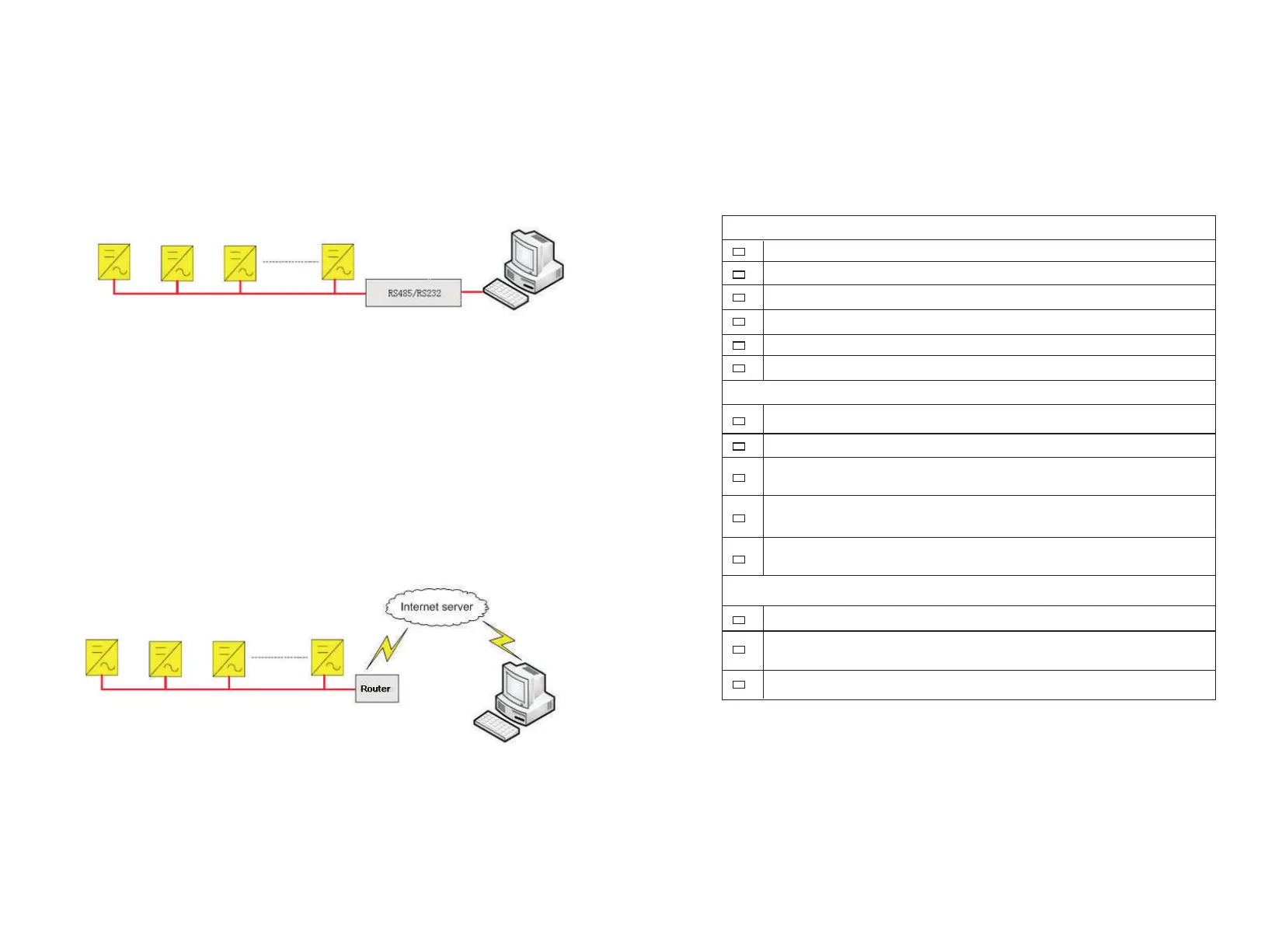
4.5.1 RS485 communication
The inverter, through RS485 tandem, is connected with the PC for communication
through RS485/RS232 adaptor. Inside the PC, a multi-machine monitoring
software ShineNet independently developed by the ATESS is monitoring in real
time the operating status of all inverters, as shown in Figure 4-5-1. The RS485
wire should be less than 1000m.
Figure 4-5-1 RS485 Multi-machine Communication
4.5.2 Internet communication
There is an Ethernet port on the right side of LCD. Please connect the LCD and
Router with Network cable; and then router can make data interaction with serve,
and users can communicate with the inverter by internet.
Figure 4-5-2 Internet Communication
4.6 Installation inspection
Before the inverter is put into operation, it shall be inspected for installation. Two
working men or more shall inspect to ensure correct installation of all installation
according to the following table.
Inverter's bottom is fixed, and the support is stable and reliable.
Enough space is left around inverter.
The ambient temperature, humidity and ventilation satisfy requirements.
Smooth flow of cooling air.
Complete and reliable sealing protection of cabinet.
No deformation and damage to inverter.
Electrical Installation Inspection
Complete and firm grounding of inverter.
Grid voltage matching the rated input voltage of inverter.
Correct phase sequence of grid connection, and tightening torque meeting
requirements.
Correct connection of DC input anode and cathode, and tightening torque
meeting requirements.
Correct connection of communication lines, and maintaining a certain
distance to other cables.
Mechanical Installation Items Inspection
Other Inspections
All useless conductive parts tied with insulating ribbon.
No tools, spare parts, conductive dust generated from drilling or other
matters left inside the cabinet.
No condensed humidity or icing inside the cabinet.
Table 4-6 Installation Inspection List