9
10
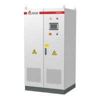
3.3 The layout of the main components
3.3.1 External components
Figure 3-3-1-1 Inverter appearance
No. Name Descripition
1
Power indicator When power supply is normal, the indicator displays
yellow.
2
Inverter malfunction indicator When inverter is faulty, the indicator displays red.
3
touch Screen LCD
Operation information display, receive control
command and parameters setting
4
Off-on knob
only control the grid-side switch, and does not
control the DC-side switch
5
Emergency STOP
Shut down the inverter when pressed down
6
Dust screen
prevent dust from entering into the inverter
Figure 3-3-1 Part description
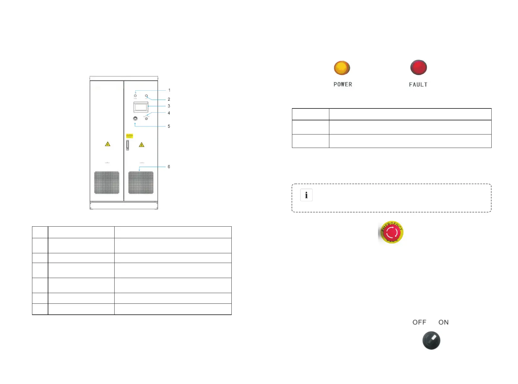
There are two LED indicators on the inverter which is used to display the current
status of the inverter.
Figure 3-3-1-2 LED indicators
LED Description
POWER
The indicator lights when power supply to the inverter is normal.
FAULT
The indicator lights when there is failure in circuit system.
Figure 3-3-2 LED status
Indicator
CAUTION
The emergency stop button is only used in case of emergency,
such as: serious failure in the grid, fire, etc.
Figure 3-3-1-3 Emergency STOP
Emergency STOP
ATESS HPS30 appearance of the structure as shown in FIG. 3-3-1-1
The emergency stop button immediately disconnects the inverter from both grid
and battery, which ensure the safety of the inverter. By pressing the emergency
stop button, the device will be locked in the "off" position. Only release the
emergency stop button by rotating it clockwise and closing AC, DC breaker, can
the inverter resume working normally.
Figure 3-3-1-4 Off-on knob
Off-on knob
It is used to start or stop the inverter.