22
21
4.6lectrical installation
4.6.1 Input and output requirements
NOTICE
Caution, risk of danger
• There is a danger of electrical shock of high voltage in inverter ’s
operation; only electricians of professional skills can operate.
•All connections with this equipment shall be done under non-voltage
state.
• The inverter may be damaged if input or output terminal is ncorrectly
plugged.
Failure of acting upon this information may cause serious
1) Battery
Battery string voltage should not exceed 720V, or else inverter will be in faulty mode
2) Three-phase grid
I nv e r t er w il l c on t i n uo u s l y i n sp e c t w h e th e r t h e g r i d s a t is f y t h e g r i d
connectedconditions. The following is the grid limit for satisfaction of local Grid
connected onditions (requirements in different countries may vary, the value can be
setup nd please refer to local grid connected regulations for details), and the grid is
hree-phase grid. Meanwhile, it shall be permitted by local power supply epartment
before install Grid-connected inverted power.
Model
HPS5000TLS/HPS7500TLS/HPS10000TLS
Grid Voltage Limit
Grid Frequency Limit
210V~250V
47HZ-51.5HZ/57HZ-61.5HZ
CAUTION!
Caution, risk of danger
The positive and negative of the battery shall not be connected in
reverse. A multimeter shall be used to determine the polarity first, and
then connect into the corresponding input ends of the inverter.Specific
procedures are as follows:
Cable (Cu)
Cable Diameter Requirements (mm²)
Model
PV +-
BAT +-
Grid input A B C
Grid input A B C
Communication Wire
Earth Wire
HPS5000TLS/HPS7500TLS/HPS10000TLS
input cable with each at least 4 mm2
cable with each at least 6 mm2
input cable with each at least 4 mm2
input cable with each at least 4 mm2
0.75mm², shielded Twisted pair is recommended
More than 6 mm².Green and yellow is recommended
Aperture
Φ5,5N*m
Φ5,5N*m
Φ5,5N*m
/
Φ5,5N*m
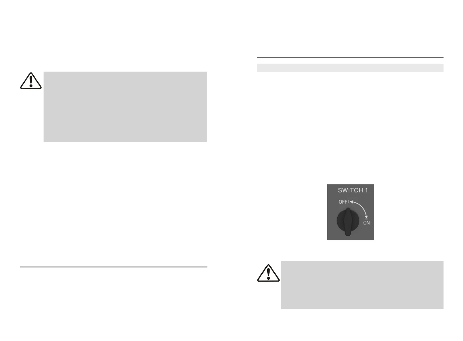
4.6.2 preparation before cable connection
Before wiring, you need to open the front door of the energy storage controller. The
specific steps are as follows:
Step 1: Turn off the AC and DC air. As shown in the figure below, the PV switch is in
the "OFF" state.
4.6.3 DC side wiring