109
3.4 The layout of the main parts
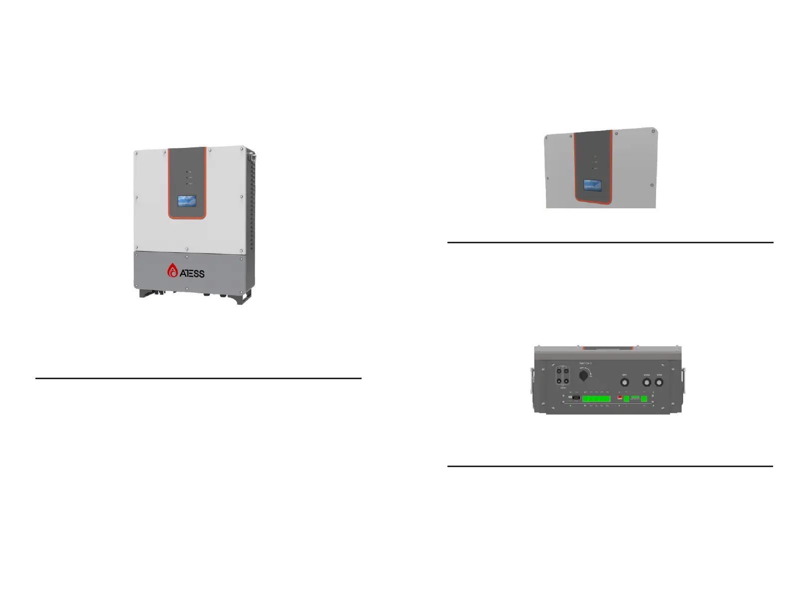
3.4.1 External layout
Figure 3-4-1-1 Inverter appearance
No.
Name
Description
1
2
3
4
Display
PD compartment
Cable inlet and outlet
Heat dissipation screen
Inverter setting, browsing and operation
status display
For power input and output installation
and maintenance
For input and output power cable
conneciton
For hot and cool air ventilation
Figure 3-3-1 Part description
Figure 3-4-1-2 LED indicators
LED
RUN
STOP
FAULT
Description
Lit when inverter is in normal operation
Lit when inverter is stopped
Lit when inverter is in fault condition
Port
SWITCH I
INPUT I
BAT/LOAD/GRID
Description
PV DC switch
PV cable gland
Cable gland for input and output
Cable inlet and outlet
Figure 3-4-1-3 Inverter cable inlet and outlet
Indicator
There are 3 LED indicators on the inverter which is used to display the current
status of the inverter.