23
- The power supply must be connected directly to the network after
the all-pole cut-off device in accordance with the installation rules.
- If the power cable is damaged, it must be replaced by the
manufacturer, its After-Sales service or a similarly qualified
professional to prevent any hazards.
- If using the pilot wire, and if it is protected by a 30 mA residual
current device (e.g. bathroom), the pilot wire power supply needs to
be protected on this RCD.
- If you wish to use a load-shedding device, select one with a pilot
wire output and not with a power output, to avoid damage to the
thermostat.
Remote control
- You can control your appliance remotely, by sending it Comfort,
Comfort -1, Comfort -2, Eco, Off and Frost Protection commands via
an interface with a 6-command pilot wire connected to a bridge (set
the corresponding Comfort and Eco temperatures on the appliance).
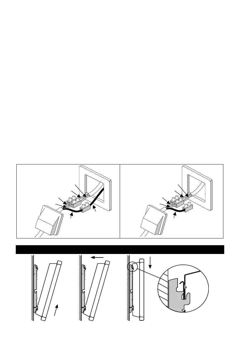
Appliance wiring diagram
Switch off the power supply and connect the wires according to
your installation: