LRP200000228 Issue A 15
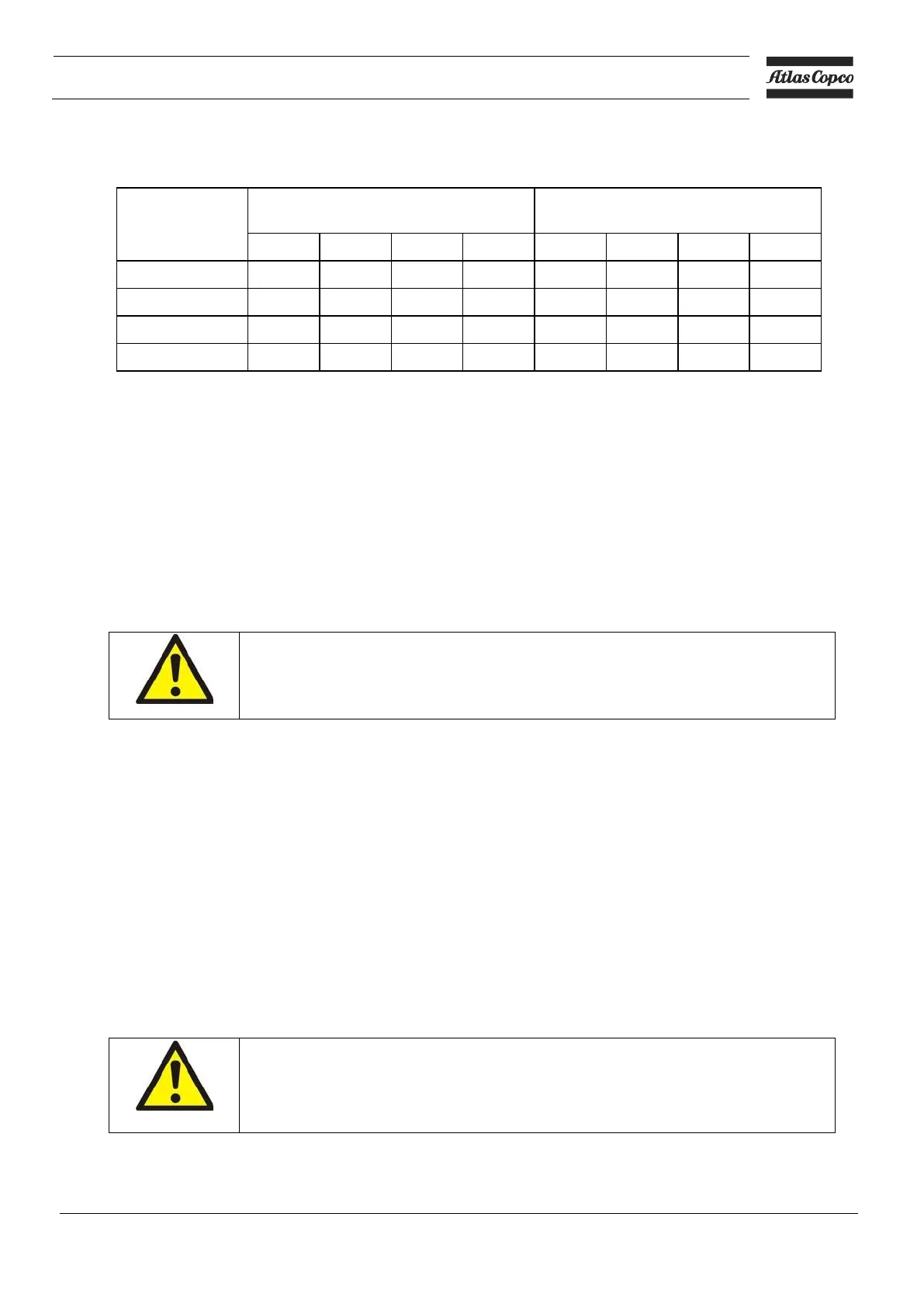
Table 11 – Maximum inlet/outlet connection loading forces and moments
Maximum external forces (N) on
inlet/outlet connections
*
Maximum external moments (Nm) on
inlet/outlet connections
†
* F
X,
F
Y
and F
Z
are the forces in each of the X, Y and Z directions (see below) and FR is the total resultant
force.
† MX, MY and MZ are the moments in each of the X, Y and Z directions (see below) and MR is the total
resultant moment.
X is the horizontal direction, parallel to the drive shaft.
Y is the horizontal direction, at 90° to the X direction.
Z is the vertical direction from the base of the pump upwards.
3.3 Pumping system design
3.3.1 General
WARNING
Obey the safety instructions listed below and take note of appropriate
precautions when you install the pump.
• The gases to be pumped must be free of solids. If necessary, incorporate an inlet filter in the inlet
pipeline to the pump, to prevent the ingress of solids into the pump.
• Make sure that the process outlet pipeline cannot become blocked. If you have an outlet-isolation valve,
make sure that you cannot operate the pump with the valve closed.
• Install a non-return valve in the inlet pipeline, to prevent the reverse-flow of sealing liquid into your
system when the pump is switched off.
• Provide for a purge of inert gas when you shut down the pumping system, to dilute dangerous gases to
safe concentrations.
• Design your pumping system such that, if it is shut down automatically, it cannot restart automatically
without being reset manually.
3.4 Sealing liquid system design
3.4.1 Introduction
WARNING
You must not start the pump if the level of sealing liquid is above the pump
auto drain valve centre line. To avoid this, configure the pump as shown in
Figure 1, detail A, B or C and start-up the pump as described in Section 4.2.
Your pump may be supplied with a sealing liquid system fitted, configured in one of three ways, as
described in Sections 3.4.2 to 3.4.4.
 Loading...