2920 1251 02
13
Instruction book
outlet of compressor element (E) decreases, valve (V3)
closes by spring force and stops blowing off air.
7. Valve (V2) allows the small flow of air, which remains
drawn in through by-pass hole (5), to blow off from
receiver (AR) via flexible (2) to unloader (UA).
8. Air delivery is stopped (0 %), the compressor runs
unloaded.
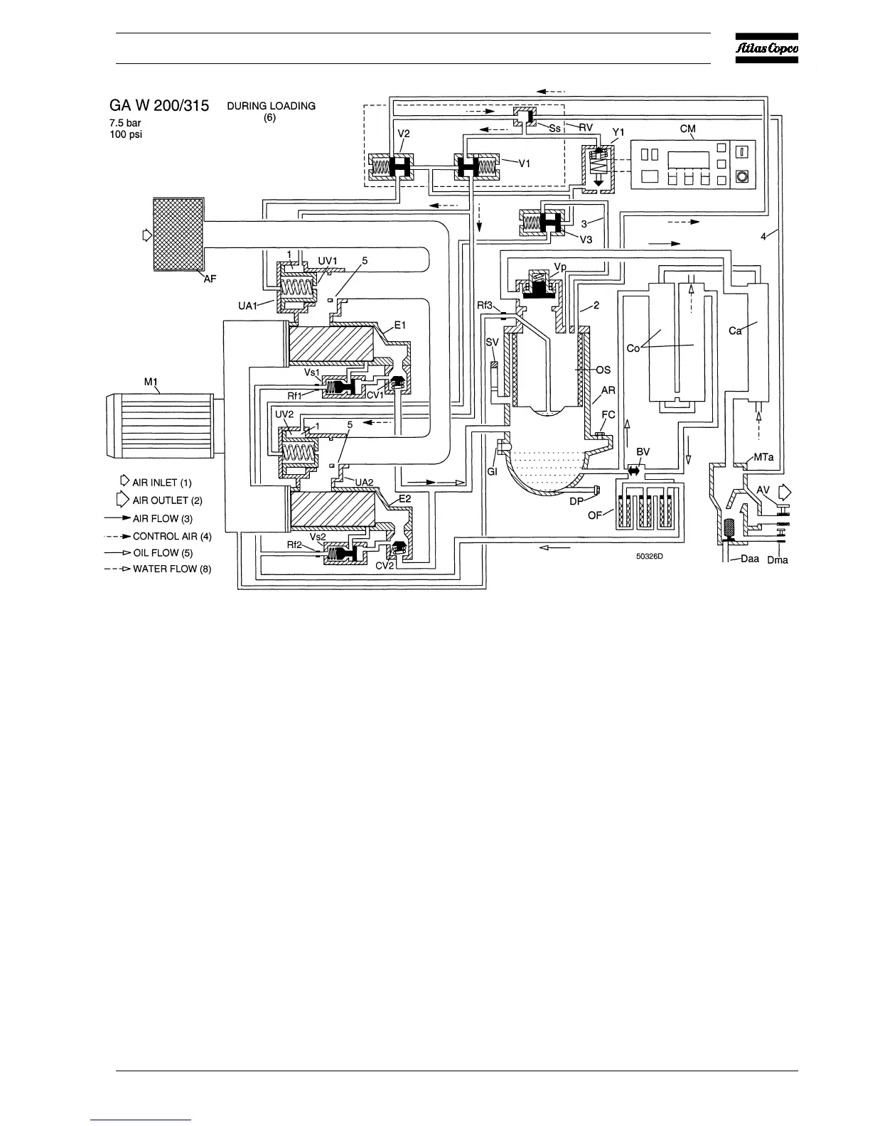
GA/GA W 200 up to -315
1. Control pressure is fed via flexible (2) and selector valve
(Ss) through solenoid valve (Y1) to valves (V1, V2 and
V3).
2. The plungers of valves (V1, V2 and V3) move against
spring force.
3. Control pressure present in chambers (1) of unloaders
(UA1 and UA2) is vented to atmosphere through valve
(V1). Unloading valves (UV1 and UV2) close by spring
force.
4. For 7.5 bar/100 psi compressors, receiver pressure is
released:
- through flexible (2) and valve (V2) to unloader (UA1)
- through flexible (3) and valve (V3) to unloader (UA2)
5. For 10/13 bar/125/150/200 psi compressors, receiver
pressure is released:
- through flexible (2) and valve (V2) to unloaders (UA1
and UA2)
- through flexible (3) and valve (V3) to unloaders (UA1
and UA2)
6. As the receiver pressure decreases, selector valve (Ss)
switches over.
7. Valves (V2 and V3) allow the small flow of air, which
remains drawn in through by-pass holes (5), to blow off
from receiver (AR) via flexibles (2 and 3) to unloaders
(UA1 and UA2).
8. Air delivery is stopped (0 %), the compressor runs
unloaded.
Fig. 5d GA W 200 up to -315 during loading (7.5 bar/100 psi)
 Loading...