2920 1381 02
22
Instruction book
6. Connect the automatic condensate drain outlet (Daa-Fig.
1.5) to the drain collector.
7. On water-cooled compressors, drain valves should be fitted
by the customer in the water inlet and outlet pipes. Also
provide and open the water inlet and regulating valve.
Consult section 2.6 for the water requirements.
8. Check the oil level. The pointer of the level gauge (Gl-Fig.
3.5) should register in the green or orange range. The bottle
with Atlas Copco Roto-injectfluid (4-Fig. 3.1) can be used
for topping up. Check section 3.2 for lubrication of the
compressor element.
9. Labels are delivered with the compressor, warning the
operator that:
- the compressor automatically restarts after voltage
failure (see section 1.3.1)
- the compressor is automatically controlled and may be
restarted, even after manually stopping (see section
1.3.1)
Stick these labels on an obvious place near the control
panel. Read these warnings (as well as the warnings
mentioned in section 1.3.1) and take them into
account.
10.Switch on the voltage. Start the compressor and stop it
immediately. Check the rotation direction of the motors.
First check the drive motor (M1-Fig. 1.3). The correct
rotation direction is indicated by an arrow (2-Fig. 1.3)
provided on the gear casing (rotation direction depends on
compressor type). If the rotation direction is wrong, switch
off the voltage and reverse two incoming electric lines.
Then check fan motor (M2-Fig. 1.3) on air-cooled
compressors. Rotation arrows, visible through the grating
in the roof, are provided on the plate below the fan. If
necessary, switch off the voltage and reverse two incoming
electric connections at the terminals of circuit breaker (Q15-
Fig. 1.7).
11. Check the programmed settings. 1)
12.Start and run the compressor for a few minutes. Check that
the compressor operates normally.
3.2 Before starting
If the compressor has not run for the past 6 months, it is strongly
recommended to improve the lubrication of the compressor
element at starting: Disconnect inlet pipe (2-Fig. 1.4), remove
unloader (UA-Fig. 1.3) and pour 3/4 l of oil into the compressor
element. Reinstall the unloader and reconnect the pipe. Make
sure that all connections are tight.
1. Check the oil level (Gl-Fig. 3.5). The pointer should register
in the green range or in the orange range.
2. If the coloured part of the air filter service indicator (VI-
Fig. 3.6) shows full out, replace the air filter element (AF).
Reset the service indicator by pushing its knob and reset
the service warning 11).
On water-cooled compressors also:
3. Check that the cooling water drain valves (customer’s
installation) in the inlet and outlet pipes are closed.
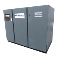
Fig. 3.2 Gear casing/motor
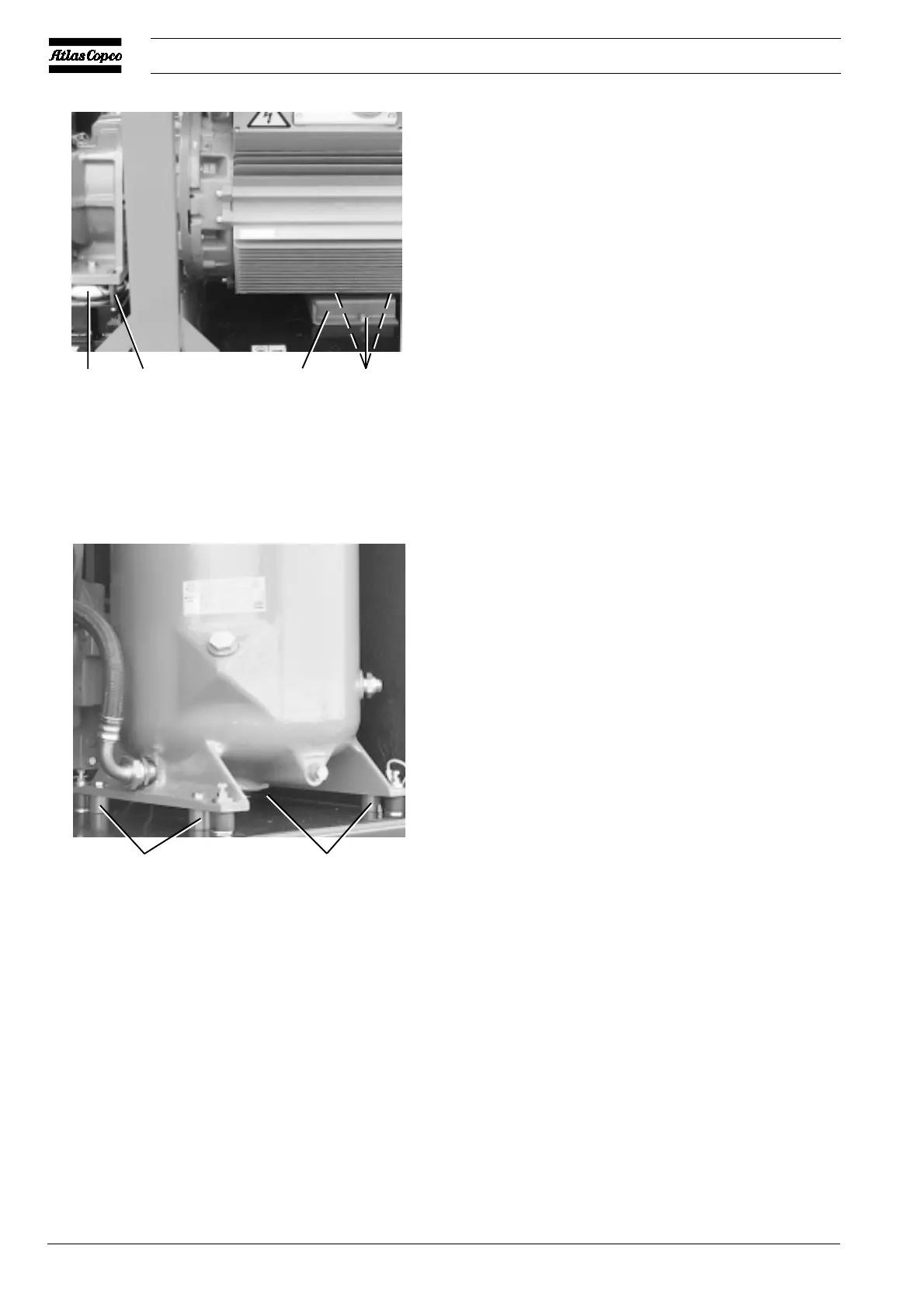
Fig. 3.3 Air receiver
1 Vibration damper
2 Bush, to be removed
3 Support, to be removed
4 Bolt
5 Bush, to be removed
Figs. 3.2 and 3.3 Transport fixations
4
50342F
12 3
55
50510F
 Loading...