Hydraulic oil
In order to protect the environment, use of
biologically degradable hydraulic oil is
recommended. No other fluids must be used.
◆
Viscosity (preferred) 20-40 cSt.
◆
Viscosity (permitted) 15-100 cSt.
◆
Viscosity index minimum 100.
Standard mineral or synthetic oil can be used.
Make sure to only use clean oil and filling
equipment.
When the machine is used continuously, the oil
temperature will stabilise at a level which is called
the working temperature. This will, depending on
the type of work and the cooling capacity of the
hydraulic system, be between 20-40°C (68-104°F)
above the ambient temperature. At working
temperature, the oil viscosity must be within the
preferred limits. The viscosity index indicates the
connection between viscosity and temperature. A
high viscosity is therefore preferred, because the
oil can then be used within a wider temperature
range. The machine must not be used, if oil
viscosity fails to remain within the permitted area,
or if the working temperature of the oil does not fall
between 20°C (68°F) and 70°C (158°F).
NOTICE The setting of the pressure relief valve
on the machine can in some cases be higher than
the prescribed maximum setting according to the
EHTMA category, see "EHTMA category". A too
high pressure relief valve setting can harm the
machine to be used. Readjust the pressure relief
valve, if the technical specifications of the machine
prescribe a lower pressure relief valve setting than
the standard setting of the machine.
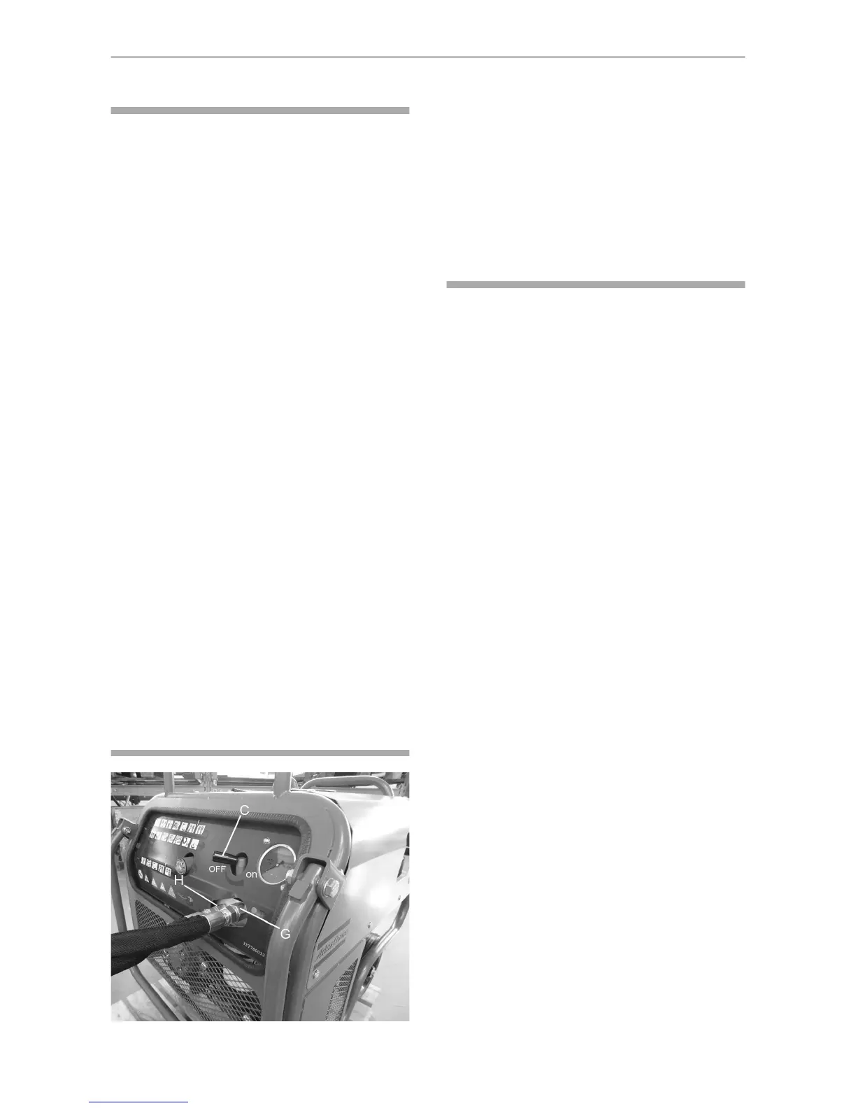
Hydraulic control and
connectors
The by-pass valve (C) must be in the OFF position
when starting and in the ON position when using
the machine.
Connectors (G) and (H) are used to connect the
power pack to the machine as follows:
◆
Connector (G) = Return (female quick-release
coupling).
◆
Connector (H) = Feed (male quick-release
coupling).
Hoses and connections
Ensure that the machine you plan to use is
compatible with the model of power pack being
used. Otherwise, both the power pack and the
machine might be harmed. Check the "Technical
data" in this instruction book and compare the flow
rate with the technical specifications in the
instruction book for the machine.
Connecting hoses
1. Turn the by-pass valve to the OFF position and
stop the engine.
2. Make sure the couplings are clean and
serviceable.
3. Attach the return line hose and the feed line
hose.
4. Start the engine and run the power pack to fill
up the hydraulic circuit. Check the hydraulic oil
level.
Disconnecting hoses
1. Turn the by-pass valve to the OFF position and
stop the engine.
2. Remove the feed line hose and the return line
hose.
The couplings are unlocked by moving the collar
back on the coupling.
Hose length
For power packs giving a flow of 20 l.p.m. (5 US
gal/min), a maximum hose length of 21 m (69 ft) is
recommended. For power packs giving a higher
flow, a maximum hose length of 14 m (46 ft) is
recommended.
Normally, 7 m (23 ft) of Twin hose is used for the
power pack.
Twin hoses and other accessories are shown in
the spare parts list.
Safety and operating instructions LP 13-30 P
12 © Construction Tools EOOD | 3392 5254 01 | 2017-04-13
Original instructions
 Loading...