PAGE
8
Repair Instruction No. 169.2/94
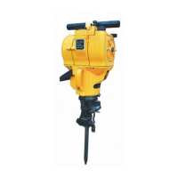
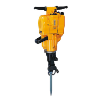
PHE 24/26/30-Range
1 Insert the rubber shell (4).
2 Insert the centering ledges (2) in the
field (3).
3 Insert the field (3) in the motor housing (5)
by hitting it lightly on the rear.
4 Insert the air deflector plate (1).
Mounting the
field
F
Please additionally secure all screwed connections in metal with screw locking device.Note
Assembly
1
12345
12345
2
1 Insert the armature (4) in the end shield
(1) by hitting the armature shaft lightly
with a plastic hammer.
2 Turn armature until the reliefs for the end
shield screws (2) are released. Fasten the
armature with screws (4 Nm).
3 Insert the armature with end shield in the
motor housing (5). Push together the end
shield and the motor housing (if
necessary hit it lightly with a plastic
hammer).
Mounting the
armature
1 Insert the carbon brush holders (6).
2 Insert the carbon brushes (5) and hang up
the tension springs (4) with clasp.
3 Insert the AVS-rubber (2) and the guiding
rollers (3).
4 Mount the handle cover (1) on the motor
housing.
5 Insert the electrical parts in the handle
cover and connect them according to the
connection diagram.
F
Make sure the cables fit properly in the
housing. Cables must never be jammed
when assembling.
Assembling the
electrical parts
3
transparent
violet
grey
A1
E1
E2
A2
red
blue
black
yellow
21 3
grey
12 3 4563
PHE 24/26 PHE 30 RX 2
Electronicswitch
A1
E2
E1 A2
blue
red
black
red
violet
Yellow
 Loading...