16 1310 3011 73
position after it’s initial setup. REUSE OF LOCKNUTS
IS STRICTLY PROHIBITTED BY ATLAS COPCO
1
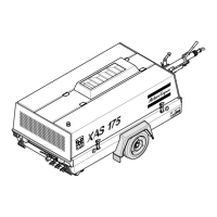
Fig. 3.1A Drawbar
3
2
4
5
5
6
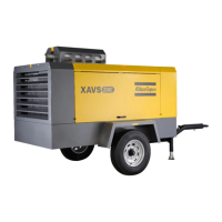
Fig. 3.1B Drawbar
8
7
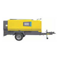
Fig. 3.1C Drawbar
3.1.2 Parking Instructions (see Fig. 3.2)
When parking a compressor, secure prop (1) or nose wheel
to support the compressor in a level position. Place the
compressor as level as possible; however, it can be
operated temporarily in an out-of-level position not
exceeding 15
°. If the compressor is parked on sloping
ground, immobilize the compressor by placing wheel
chocks in front of or behind the wheels. Locate the
compressor upwind, away from contaminated wind-streams and
walls. Avoid recirculation of exhaust air from the engine. This
causes overheating and engine power decrease.
3.1.3 Towing Instructions
Before towing the compressor, make sure that the towing
equipment of the vehicle matches the towing eye or ball
connector
The drawbar should be as level as possible and the compressor
and towing eye end in a level position. Secure nose prop (1) in
the highest position. Attach safety chains/cables in a criscross
manner to the tow vechical. This will help prevent the towbar
from contacting ground in event of a breakaway. Connect road
lights when applicable.
3.1.4 Lifting Instructions
When lifting the compressor, the hoist has to be placed in such
a way that the compressor, which must be placed level, will be
lifted vertically.
Ue the lifting bale provided to lift the unit.
f Lifting acceleration and retardation must be kept
within safe limits (max. 2xg).
Helicopter lifting is not allowed.
3.2 Before Starting
f If the compressor is to be connected to a common
compressed air system, fit an appropriate check
valve between compressor outlet and air system.
Observe the right mounting position/direction!
1. Before initial start-up, prepare battery for operation if not
already done. See section 4.7.
2. With the compressor standing level, check the level of the
engine oil. Add oil, if necessary, to the upper mark on
dipstick. Consult the Engine Operation Manual for the type
and viscosity grade of the engine oil.
3. Check the level of the compressor oil. The pointer of oil
level gauge (OLG- Fig. 2.3) should register in the green
range. Add oil if necessary. See section 4.3 for the oil to
be used.
f Before removing oil filler plug (FP- Fig. 2.3), ensure
that the pressure is released by opening an air outlet
valve.
4. Check that the fuel tank contains sufficient fuel. Top up, if
necessary. Consult the Engine Operation Manual for the
type of fuel.
5. Drain any water and sediment from the fuel filter until clean
fuel flows from the drain cock.
6. Press vacuator valve (VV- Fig. 2.3) of the air filter to
remove dust.
7. Check the air filter service indicator (VI- Fig. 2.3). If the red
part shows completely, service or replace the filter element.
Reset the indicator.
8. Open an air outlet valve (AV-fig. 2.2) to allow air flow to the
atmosphere.
 Loading...