14 1310 3011 73
Electrical System
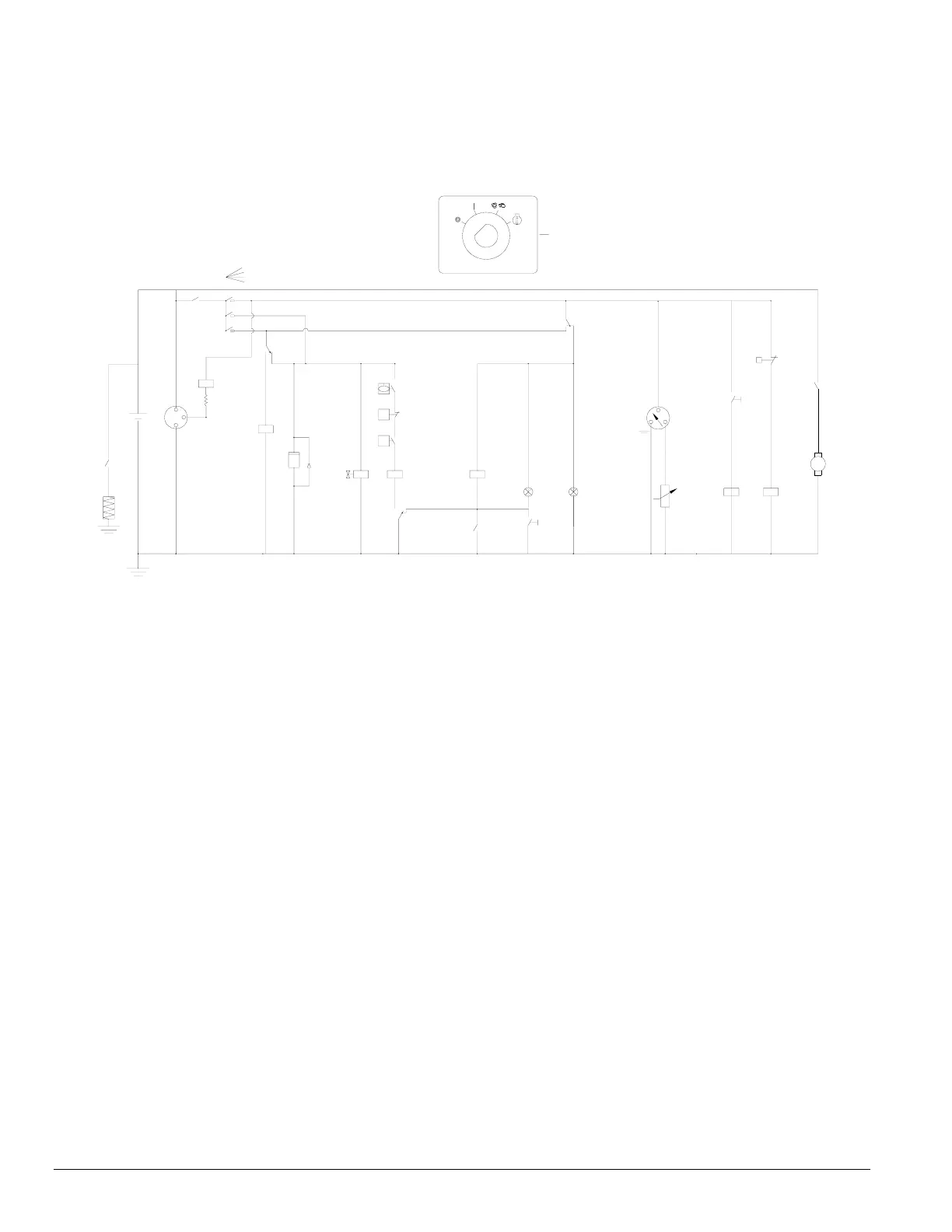
2.7.1 Circuit Diagram
44
86
85
HTR
B+
K5
87
30
-
B-
D+
G2
+
G1
K4
15
12 12
12
12
30
87
K1
87a
12
K2
30
87
P1
K0
h
26
V2
Y1
27
8
87
K4
87a
3
6
K3
85
86
P
S3
87
30
30
86
85
K2
3
3
S2
S6
87a
9
5
S1
12V DC
10A
F1
2
3
2
3
3
1
2
1
0
S1
87a
87
S7
12
12
S4
12
H1
H2
Temp
GENERAL
ALARM
85
99
30
11
K1
86
S5
87a
M1
S
M
K0
P2
+
87
K3
30
012 3
2
12
86
K5
85
30
S8
R1
Figure 2.7 Circuit diagram
F1 Circuit breaker
G1 Alternator
G2 Battery
H1 Temperature alarm lamp
H2 General alarm lamp
HTR Air inlet preheat
K0 Starter solenoid (part of M1)
K1 Relay
K2 Relay
K3 Relay
K4 Relay
K5 Relay
M1 Starter motor
P1 Hour meter
P2 Fuel Level Gauge
S1 Contact switch (Off-On-Override-Start)
S2 Temperature switch engine
S3 Oil pressure switch engine
S4 Lamp test switch
S5 Temperature switch (Compressor)
S6 Low Fuel Level switch
S7 Fuel Level sender
S8 Preheat Pushbutton
Y1 Fuel solenoid valve
R1 Resistor
V2 Diode
 Loading...