12 1310 3011 08
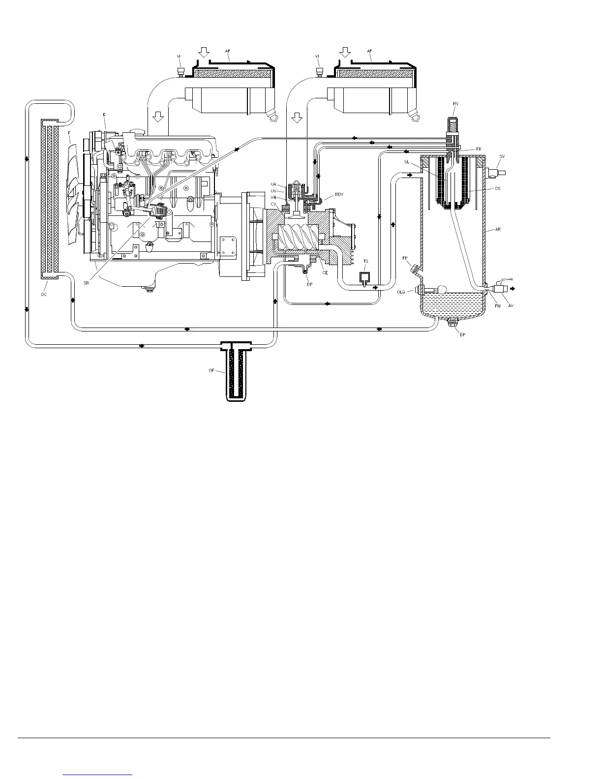
Fig. 2.3 Compressor Regulating System
AF Air Filter
AR Air Receiver
AV Air Outlet Valves
BDV Blow Down Valve
CE Compressor Element
CV Check Valve
DB Drive Belt
DP Drain Plug
E Engine
F Fan
FN Flow Nozzle
FP Filling Plug
FR Flow Restrictor
OC Oil Cooler
OF Oil Filter
OLG Oil Level Gauge
OS Oil Separator
PG Pressure Gauge
RV Regulating Valve
SL Scavenge Line
SR Speed Regulator
SV Safety Valve
TS Temperature Switch
UA Unloader Assembly
UV Unloader Valve
VH Vent Hole
VI Vacuum Indicator
2.4 Air Flow (See Fig. 2.3)
The system comprises:
AF Air filter
AR/OS Air receiver/oil separator
CE Compressor element
UA/UV Unloader assembly with unloader valve
BDV Blow-down valve
FN Flow nozzle
Air drawn through the airfilter (AF) into the compressor
element is compressed. At the element outlet, compressed
air and oil pass into the air receiver/oil separator (AR/OS).
The check valve prevents blow-back of compressed air when the
compressor is stopped. In the air receiver/oil separator AR//OS),
most of the oil is removed from the air/oil mixture: the remaining
oil is removed by the separator element.
The oil collects in the receiver and on the bottom of the separator
element.
The air leaves the receiver via a flow nozzle (FN) which prevents
the receiver pressure from dropping below the minimum working
pressure, even when the air outlet valves are open. This ensures
adequate oil injection and prevents oil consumption.
A temperature switch (TS) and a working pressure gauge (PG) are
comprised in the system.
A blow-down valve (BDV) is fitted in the unloader assembly to
automatically depressurize the air receiver (AR) when the
compressor is stopped.
 Loading...