18
Instruction Manual
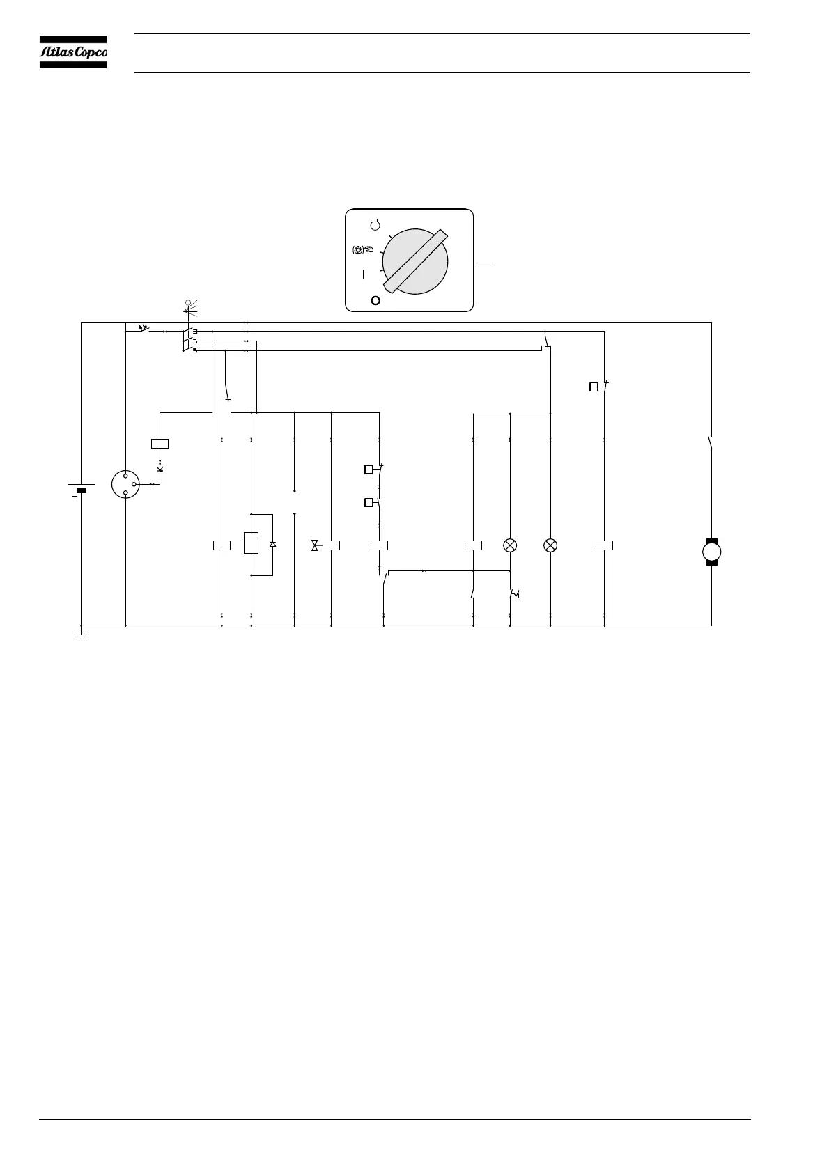
2.8 ELECTRICAL SYSTEM
2.8.1 CIRCUIT DIAGRAM (STANDARD)
The compressor is equipped with a negative earthed system.
Fig. 2.4 Circuit diagram (No. 9822 0797 01)
F1 Circuit Breaker (10 A) M1 Starter Motor
G1 Alternator P1 Hourmeter
G2 Battery S1 Contact Switch (Off-On-Override-start)
H1 Temperature Alarm Lamp S2 Temperature Switch Engine
H2 General Alarm Lamp S3 Oil Pressure Switch Engine
K0 Starter Solenoid (part of M1) S4 Lamptest Switch
K1 Shut-down Relay S5 Temperature Switch Compressor
K2 Blocking Relay Y1 Fuel Solenoid Valve
K3 Override Start Relay V1 Diode
K4 Start Relay V2 Diode
S1
3
2
1
0
q
q
21
20
6
8
7
9
24
25
28
29
3
5
4
21
8«
7«
1«
2«
12
14
4«
3«
26
27
12«
34
35
9´,10´,11´
p
12V DC
5«
Te mp
K1
General
alarm
(Lamp-
tester)
13«
15«
14«
11
10
13
11999
15
14
Auxiliary
33338
18
1615
4
3
2
1
3
2
1
0
32
33
31
30
5
10A
2322
19
17
6
7
6«
D-
D+
B+
+
M
M1
K0
S2
S3
G2
G1
K4
F1
S1
K4
K3
S5
K1H2H1K2
S4
K2
1212
V1
h
12121212121212
K3Y1
P1
K0
V2
10
13
 Loading...