37
Instruction Manual
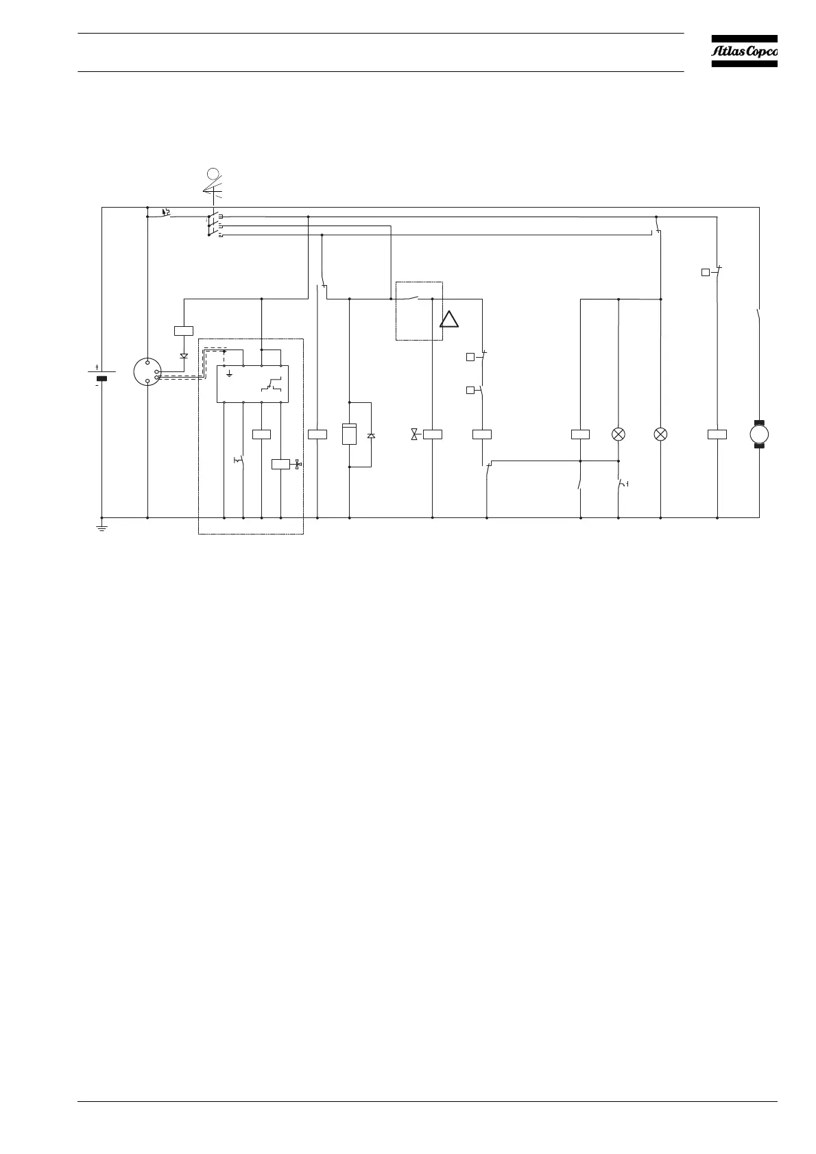
2.8.11 CIRCUIT DIAGRAM REFINARY EQUIPMENT (ALL TYPES)
Fig. 2.15 Circuit diagram (No. 9822 0909 00)
F1 Circuit breaker (10 A) S1 Contact switch (Off-On-Override-start)
G1 Alternator S2 Temperature switch engine
G2 Battery S3 Oil pressure switch engine
H1 Temperature alarm lamp S4 Temperature lamptest switch
H2 General alarm lamp S5 Temperature switch compressor
K0 Starter solenoid (part of M1) S32 Test button overspeed
K9 Aux. relay safety circuit Y1 Fuel solenoid valve
M1 Starter motor Y20 Solenoid for overspeed protection valve
N1 Overspeed module V1 Diode
P1 Hourmeter V2 Diode
G1
G2
B+
D+
W
D-
M1
M
K1H1 H2
86
85
K2K3
S2
K9
3A
S3
Y1
P1
K0
Y20
S32
K9
N1
V1
K4
K4
V2
K1
K2
86
87a
87a
399119
30
87
30
87
K3
S5
K0
87a
87a
u
30
30
30
86
87
1
87a
87
30
87
30
85
86
85
86
85
86
85
86
283
85
6
7
86
85
87
21
20
22 23
30
15
87a87
10
30
30
14
13
30
S4
Te mp
General
alarm
(Lamptester)
See Note 1
See Note 1
12V DC
12 12 12 12 12
h
12 12 12 12 12 12 12
S1
F1
0
1
2
3
2
3
4
5
10A
2
1
3
4
u
p
1438
6527
 Loading...