36
Instruction Manual
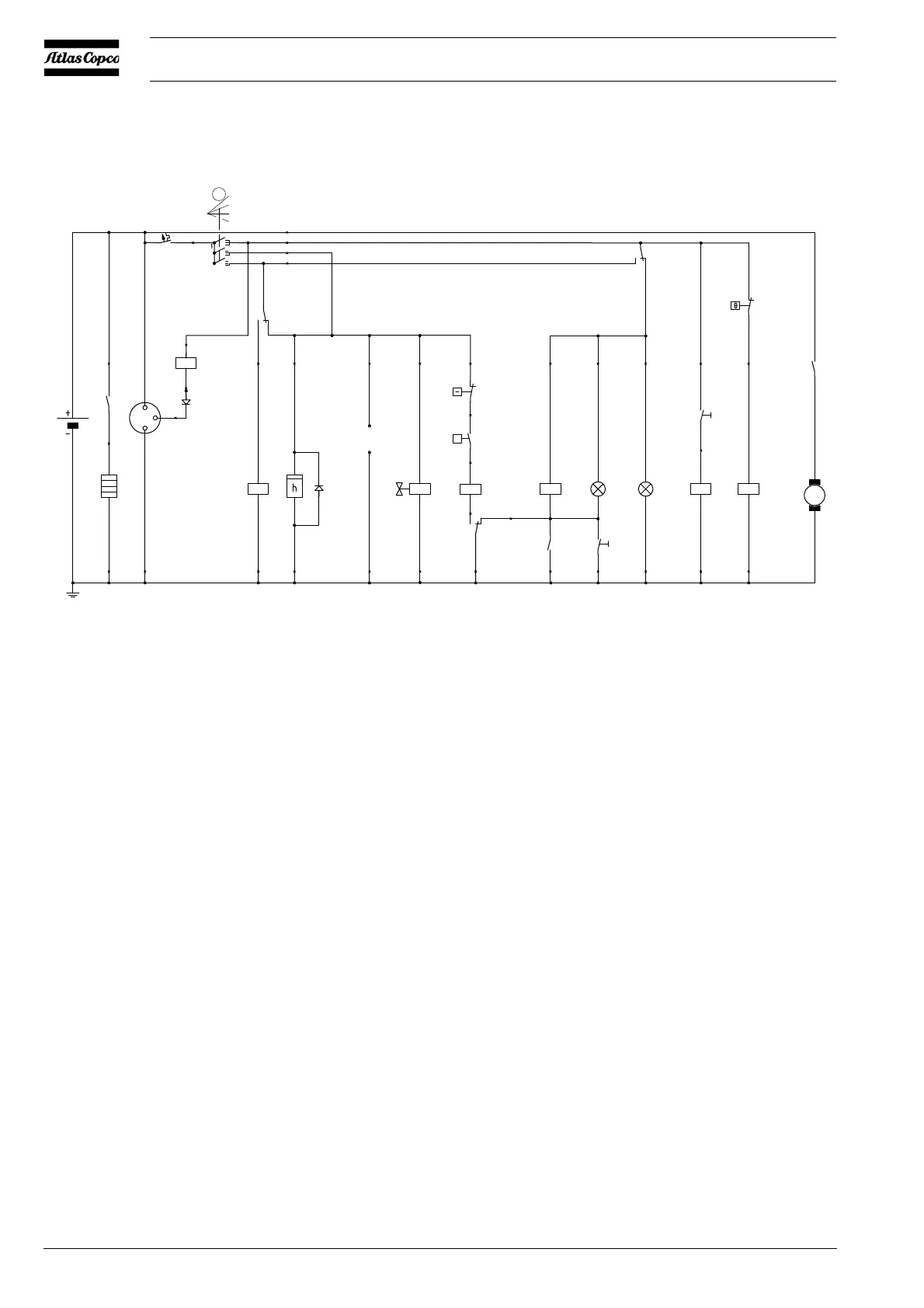
2.8.10 CIRCUIT DIAGRAM COLD START (ALL TYPES)
Fig. 2.14 Circuit diagram (No. 9822 0864 00)
F1 Circuit breaker (10 A) S1 Contact switch (Off-On-Override-start)
G1 Alternator S2 Temperature switch engine
G2 Battery S3 Oil pressure switch engine
H1 Temperature alarm lamp S4 Temperature lamptest switch
H2 General alarm lamp S5 Temperature switch compressor
K0 Starter solenoid (part of M1) S6 Push button glowplug
M1 Starter motor Y1 Fuel solenoid valve
P1 Hourmeter V1 Diode
P2 Glowplug V2 Diode
V1
K4
K5
F1
K4
S2
S3
K3
K2 H1
S4
H2
K2
K1
Y1
K0
P1
V2
G1
G2
P2
B+
D+
D-
7
6
2
85
86
30
87
8 3 3 3 3
9 9 9 2
16
11
87a
87
86
87
87
30
30
87a
85
15
10
30
30
13
14
87a
K3
S5
K0
M1
M
S6
K1K5
30
30
30
87
87
86
85
86
85
86
85
87a
87a
5
10A
Te mp
General
alarm
(Lamptester)
12V DC
0
p
S1
0
1
2
3
2
3
4
2
1
1
17
12 12 12 12 12 12 12 12 12 12 12 12
87
30
3
4
Auxiliary
 Loading...