47
Instruction Manual
3.3.4 FUNCTION OF GENERATOR DDG 230/400V
AND 230V - 3PH WITH AUTOMATIC CONTROL
SYSTEM (OPTION) - FUNCTIONAL DESCRIPTION
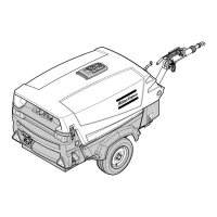
Fig. 3.27 Control panel (generator)
Generator DDG 230/400V:
H3 Lamp (green, power ON)
S7 Switch (generator - compressor)
H4 Lamp automatic control system
S8 Switch automatic control system
X1.1 Socket 400 V/ 16A
X1.2 Socket 230 V/ 16 A
*
X1.3 Socket 230 V/ 16 A
GND Terminal earth cable
Generator DDG 230V:
H3 Lamp (green, power ON)
S7 Switch (generator - compressor)
H4 Lamp automatic control system
S8 Switch automatic control system
X1.1 Socket 230 V/ 16A
**
X1.2 Socket 230 V/ 16 A
X1.3 Socket 230 V/ 16 A
GND Terminal earth cable
* For 6 kVA.
For 12.5 kVA: Socket 400V / 16A.
** For 6 kVA.
For 12.5 kVA: socket 230V / 32A.
As soon as the generator is switched on, the automatic control system
will continuously check for electric load in order to rev up the engine
from idle to nominal speed only when needed. This saves fuel and
reduces emissions.
What is more, with the current continuously monitored, a consumer
having just been switched on is temporary disconnected from the
generator to be re-connected as soon as the engine reaches nominal
speed. This is a safety mechanism to protect generator and engine
below nominal speed.
Operation with automatic control switch S8 “OFF”
– Switch generator main switch S7 “ON”.
– Generator is disconnected from socket.
– Engine reaches nominal speed.
– Generator is re-connected after 4 secs.
– Power is now available until the generator main switch S7 is
turned “OFF”.
Operation with automatic control switch S8 “ON”
– Switch generator main switch S7 “ON”.
– Generator is disconnected from socket.
– Engine reaches nominal speed.
– Generator is re-connected after 4 secs.
– If a consumer is connected, the engine goes on for 60 secs. before
falling back to idle speed.
– Generator is in standby. As soon as any consumer is switched on,
the routine is repeated from step 2.
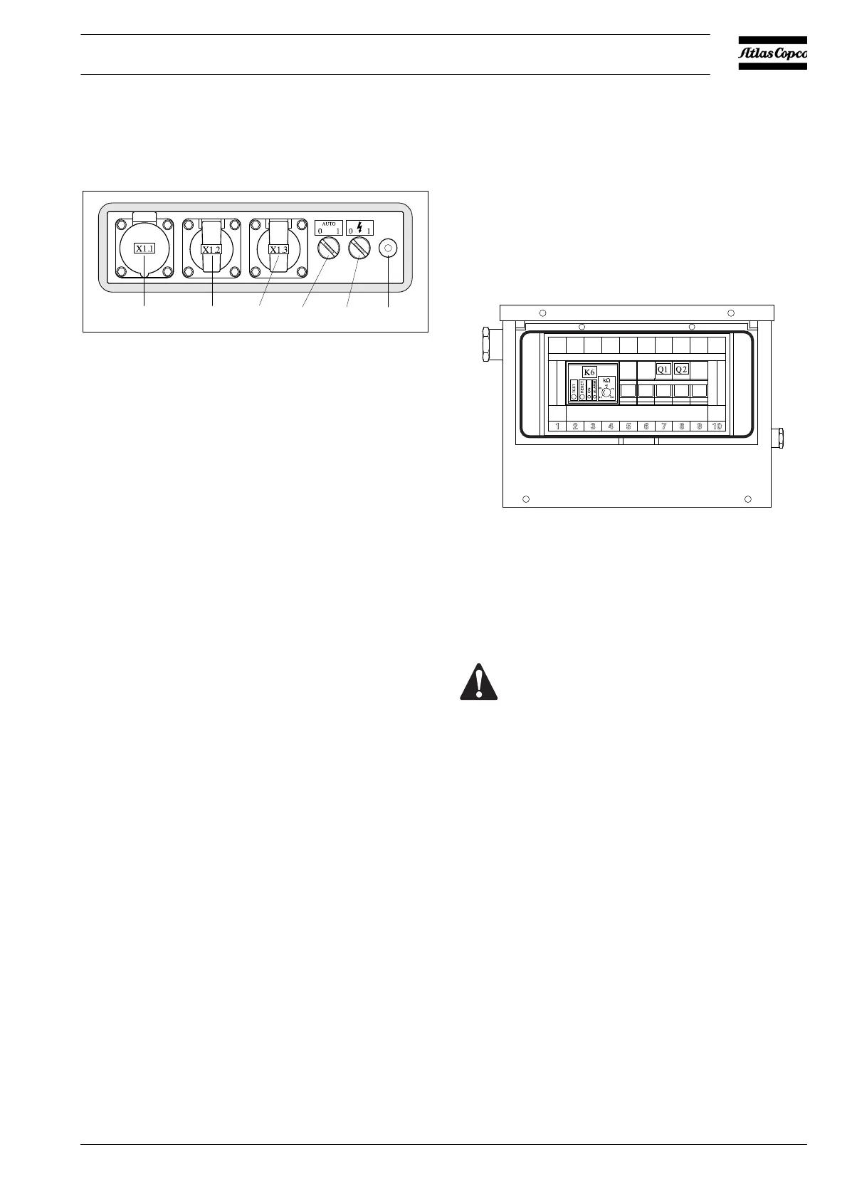
Fig. 3.28 Generator control box
Generator DDG 230/400V:
Q1 Main circuit breaker 4-pole + shunt trip coil
K6 Insulation monitoring relay
Generator DDG 230V:
Q1 Main circuit breaker 3-pole + shunt trip coil
Q2 Circuit breaker 2-pole (for 12.5 kVA only)
K6 Insulation monitoring relay
Fault situations and protective devices:
– When switching on the generator by means of the switch S7,
there is no voltage available at the sockets. Open the hood and
check if the circuit breakers are up. If the circuit breakers are
down, put them up (switch them on). Circuit breakers in the up
position can be indicative of a serious electrical fault.
– When the electrical device is connected, the circuit breakers
always switch off. This indicates a fault in the electrical device.
– When the yellow LED on the insulation monitoring relay K6 is
activated, it means that a serious insulation fault has occured.
Reset by first switching off the engine, then restart it.
– The insulation monitoring relay K6 must be adjusted to 10 kΩ.
This adjustment may not be changed.
– The thermal contact S6 closes when the temperature in the
generator becomes too high.
X1.3X1.2X1.1 H3/S7
H4/S8 GND
Before connecting an electrical device, always check the
data listed on the rating plate.
 Loading...