323
8271D–AVR–05/11
ATmega48A/PA/88A/PA/168A/PA/328/P
29.4 Clock Characteristics
29.4.1 Calibrated Internal RC Oscillator Accuracy
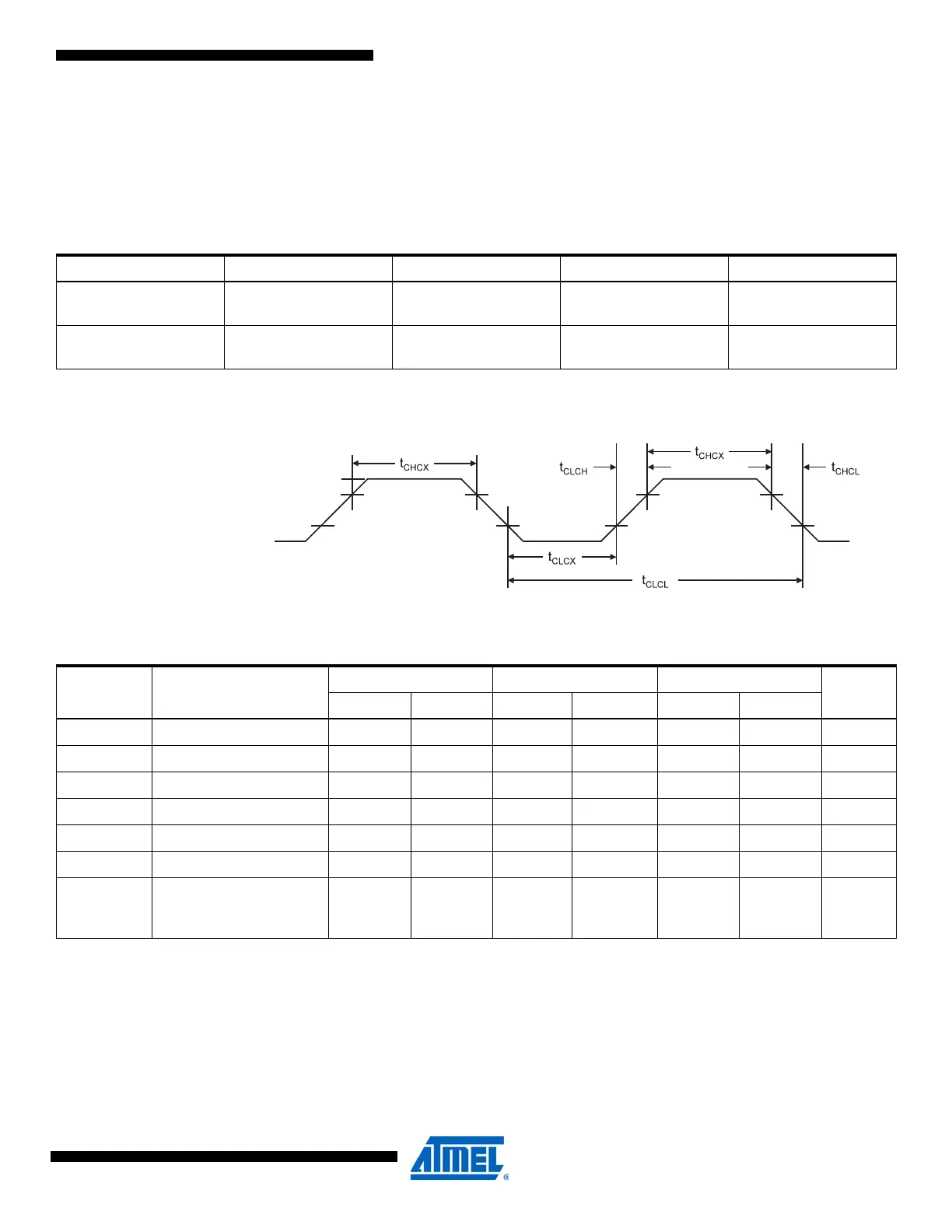
29.4.2 External Clock Drive Waveforms
Figure 29-2. External Clock Drive Waveforms
29.4.3 External Clock Drive
Note: All DC Characteristics contained in this datasheet are based on simulation and characterization of other AVR microcontrollers
manufactured in the same process technology. These values are preliminary values representing design targets, and will be
updated after characterization of actual silicon.
Table 29-10. Calibration Accuracy of Internal RC Oscillator
Frequency V
CC
Temperature Calibration Accuracy
Factory
Calibration
8.0MHz 3V 25°C±10%
User
Calibration
7.3 - 8.1MHz 1.8V - 5.5V -40°C - 85°C±1%
Table 29-11. External Clock Drive
Symbol Parameter
V
CC
= 1.8 - 5.5V V
CC
= 2.7 - 5.5V V
CC
= 4.5 - 5.5V
UnitsMin. Max. Min. Max. Min. Max.
1/t
CLCL
Oscillator Frequency 0 4 0 10 0 20 MHz
t
CLCL
Clock Period 250 100 50 ns
t
CHCX
High Time 100 40 20 ns
t
CLCX
Low Time 100 40 20 ns
t
CLCH
Rise Time 2.0 1.6 0.5 μs
t
CHCL
Fall Time 2.0 1.6 0.5 μs
Δt
CLCL
Change in period from
one clock cycle to the
next
22 2%