50
8271D–AVR–05/11
ATmega48A/PA/88A/PA/168A/PA/328/P
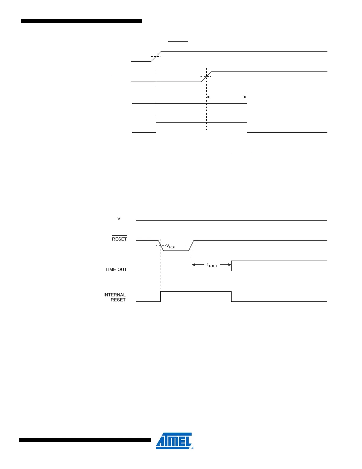
Figure 11-3. MCU Start-up, RESET Extended Externally
11.4 External Reset
An External Reset is generated by a low level on the RESET pin. Reset pulses longer than the
minimum pulse width (see ”System and Reset Characteristics” on page 324) will generate a
reset, even if the clock is not running. Shorter pulses are not guaranteed to generate a reset.
When the applied signal reaches the Reset Threshold Voltage – V
RST
– on its positive edge, the
delay counter starts the MCU after the Time-out period – t
TOUT
–
has expired. The External Reset
can be disabled by the RSTDISBL fuse, see Table 28-7 on page 299.
Figure 11-4. External Reset During Operation
11.5 Brown-out Detection
ATmega48A/PA/88A/PA/168A/PA/328/P has an On-chip Brown-out Detection (BOD) circuit for
monitoring the V
CC
level during operation by comparing it to a fixed trigger level. The trigger level
for the BOD can be selected by the BODLEVEL Fuses. The trigger level has a hysteresis to
ensure spike free Brown-out Detection. The hysteresis on the detection level should be inter-
preted as V
BOT+
= V
BOT
+ V
HYST
/2 and V
BOT-
= V
BOT
- V
HYST
/2.When the BOD is enabled, and V
CC
decreases to a value below the trigger level (V
BOT-
in Figure 11-5 on page 51), the Brown-out
Reset is immediately activated. When V
CC
increases above the trigger level (V
BOT+
in Figure 11-
5 on page 51), the delay counter starts the MCU after the Time-out period t
TOUT
has expired.
The BOD circuit will only detect a drop in V
CC
if the voltage stays below the trigger level for lon-
ger than t
BOD
given in ”System and Reset Characteristics” on page 324.
RESET
TIME-OUT
INTERNAL
RESET
t
TOUT
V
POT
V
RST
V
CC