ATtiny10/11/12
12
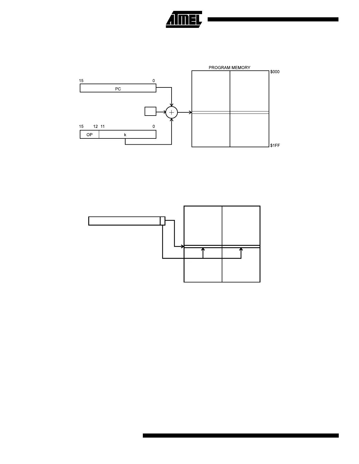
Relative Program Addressing, RJMP and RCALL
Figure 12. Relative Program Memory Addressing
Program execution continues at address PC + k + 1. The relative address k is -2048 to 2047.
Constant Addressing Using the LPM Instruction
Figure 13. Code Memory Constant Addressing
Constant byte address is specified by the Z-register contents. The 15 MSBs select word address (0 - 511), the LSB selects
low byte if cleared (LSB = 0) or high byte if set (LSB = 1).
Subroutine and Interrupt Hardware Stack
The ATtiny10/11/12 uses a 3-level-deep hardware stack for subroutines and interrupts. The hardware stack is 9 bits wide
and stores the program counter (PC) return address while subroutines and interrupts are executed.
RCALL instructions and interrupts push the PC return address onto stack level 0, and the data in the other stack levels 1-2
are pushed one level deeper in the stack. When a RET or RETI instruction is executed the returning PC is fetched from
stack level 0, and the data in the other stack levels 1-2 are popped one level in the stack.
If more than three subsequent subroutine calls or interrupts are executed, the first values written to the stack are overwrit-
ten. Pushing four return addresses A1, A2, A3 and A4, followed by four subroutine or interrupt returns, will pop A4, A3, A2
and once more A2 from the hardware stack.
+1
$1FF
$000
PROGRAM MEMORY
15 1 0
Z-REGISTER
 Loading...


