ATtiny10/11/12
42
ATtiny10/11/12
During programming, the supply voltage must be in accordance with Table 22.
Table 22. Supply Voltage during Programming
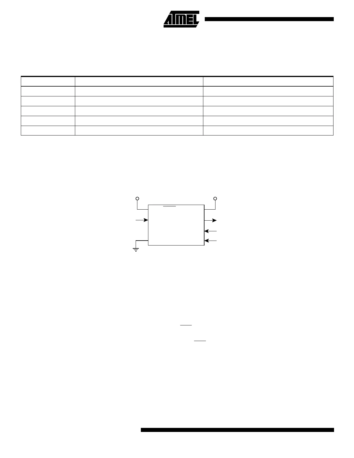
High-voltage Serial Programming
This section describes how to program and verify Flash Program memory, EEPROM Data memory (ATtiny12), lock bits
and fuse bits in the ATtiny10/11/12.
Figure 27. High-voltage Serial Programming
High-voltage Serial Programming Algorithm
To program and verify the ATtiny10/11/12 in the High-voltage Serial Programming mode, the following sequence is recom-
mended (See instruction formats in Table 23):
1. Power-up sequence: Apply 4.5 - 5.5V between V
CC
and GND. Set PB5 and PB0 to “0” and wait at least 100 ns.
Toggle PB3 at least four times with minimum 100 ns pulse-width. Set PB3 to “0”. Wait at least 100 ns. Apply 12V to
PB5 and wait at least 100 ns before changing PB0. Wait 8 µs before giving any instructions.
2. The Flash array is programmed one byte at a time by supplying first the address, then the low and high data byte.
The write instruction is self-timed, wait until the PB2 (RDY/BSY
) pin goes high.
3. The EEPROM array (ATtiny12 only) is programmed one byte at a time by supplying first the address, then the data
byte. The write instruction is self-timed, wait until the PB2 (RDY/BSY
) pin goes high.
4. Any memory location can be verified by using the Read instruction which returns the contents at the selected
address at serial output PB2.
5. Power-off sequence: Set PB3 to “0”.
Set PB5 to “1”.
Turn V
CC
power off.
When writing or reading serial data to the ATtiny10/11/12, data is clocked on the rising edge of the serial clock, see Figure
28, Figure 29 and Table 24 for details.
Part Low-voltage Serial Programming High-voltage Serial Programming
ATtiny10/11L Not applicable 4.5 - 5.5V
ATtiny10/11 Not applicable 4.5 - 5.5V
ATtiny12V 2.2 - 5.5V 4.5 - 5.5V
ATtiny12L 2.7 - 5.5V 4.5 - 5.5V
ATtiny12 4.0 - 5.5V 4.5 - 5.5V
PB5 (RESET)
PB3 (XTAL1)
GND
VCC
PB2
PB1
PB0
SERIAL DATA OUTPUT
SERIAL INSTR. INPUT
SERIAL DATA INPUT
SERIAL CLOCK INPUT
11.5 - 12.5V 4.5 - 5.5V
ATtiny
 Loading...


