ATtiny10/11/12
6
Clock Options
The device has the following clock source options, selectable by Flash fuse bits as shown:
Note: “1” means unprogrammed, “0” means programmed.
The various choices for each clocking option give different start-up times as shown in Table 7 on page 18 and Table 9 on
page 19.
Internal RC Oscillator
The internal RC oscillator option is an on-chip oscillator running at a fixed frequency of 1 MHz. If selected, the device can
operate with no external components. The device is shipped with this option selected. On ATtiny10/11, the Watchdog
Oscillator is used as a clock, while ATtiny12 uses a separate calibrated oscillator.
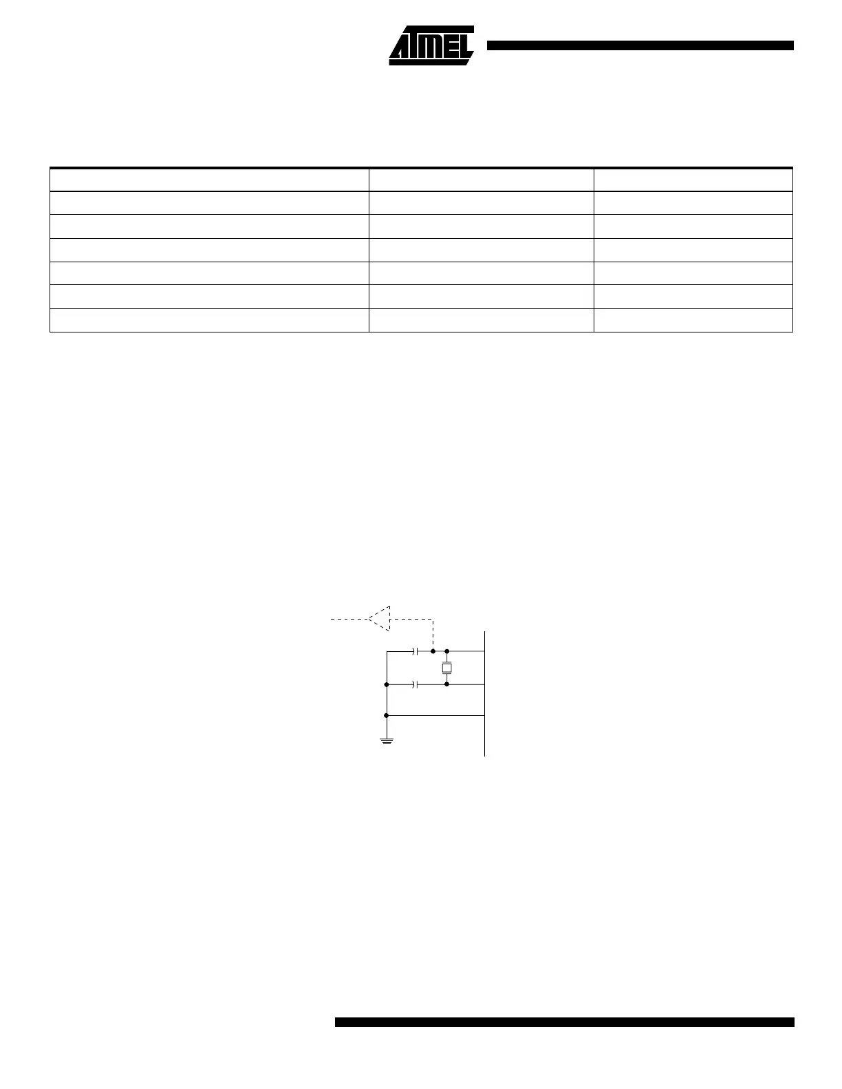
Crystal Oscillator
XTAL1 and XTAL2 are input and output, respectively, of an inverting amplifier which can be configured for use as an
on-chip oscillator, as shown in Figure 3. Either a quartz crystal or a ceramic resonator may be used.
Figure 3. Oscillator Connections
Note: When using the MCU Oscillator as a clock for an external device, an HC buffer should be connected as indicated in the figure.
Table 3. Device Clocking Options Select
Device Clocking Option ATtiny10/11 CKSEL2..0 ATtiny12 CKSEL3..0
External Crystal/Ceramic Resonator 111 1111 - 1010
External Low-frequency Crystal 110 1001 - 1000
External RC Oscillator 101 0111 - 0101
Internal RC Oscillator 100 0100 - 0010
External Clock 000 0001 - 0000
Reserved Other Options -
XTAL2
XTAL1
GND
C2
C1
MAX 1 HC BUFFER
HC
 Loading...


