ATtiny10/11/12
19
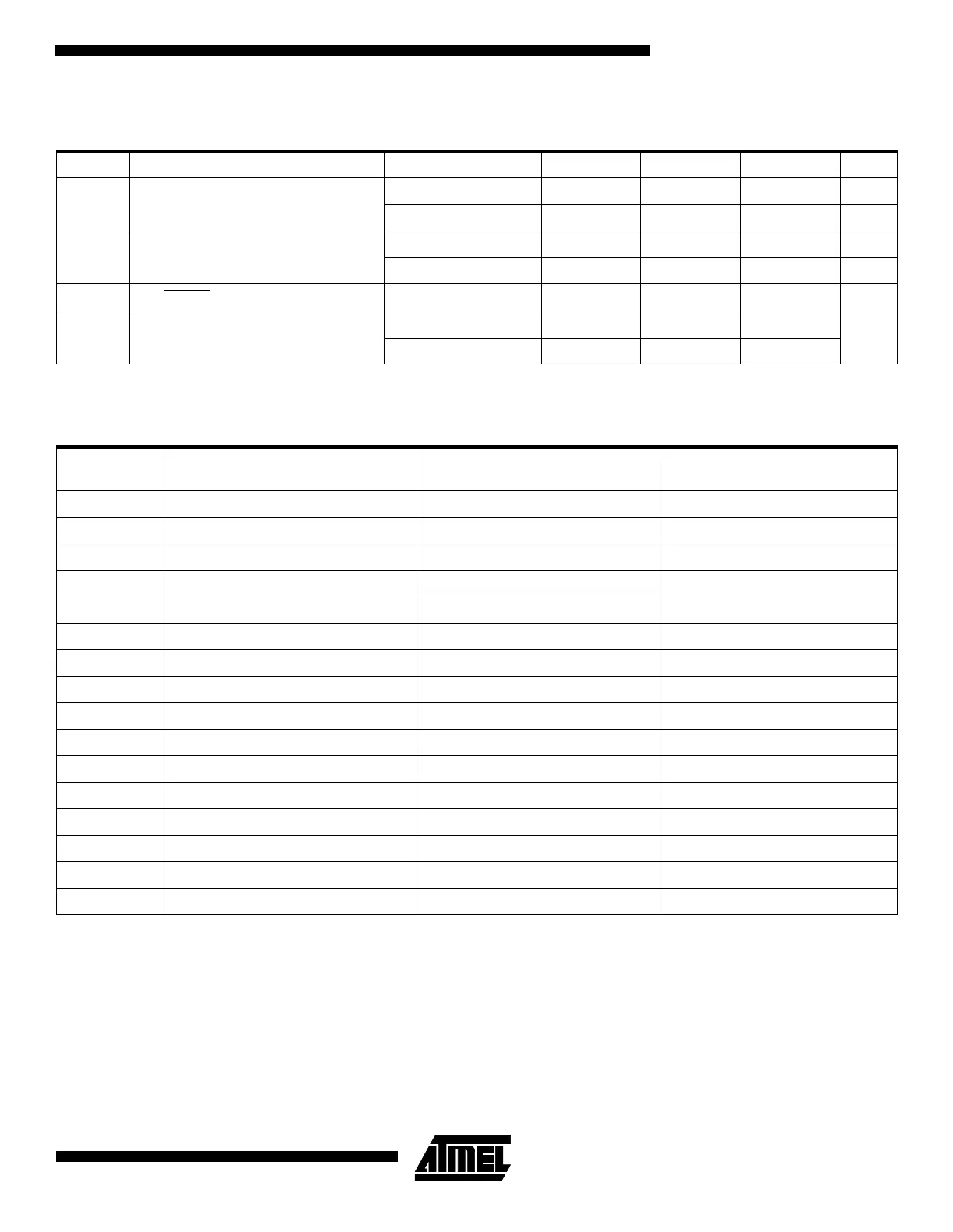
Note: 1. The Power-on Reset will not work unless the supply voltage has been below V
POT
(falling).
Note: 1. Due to the limited number of clock cycles in the start-up period, it is recommended that Ceramic Resonator be used.
This table shows the start-up times from reset. From sleep, only the clock counting part of the start-up time is used. The
Watchdog oscillator is used for timing the real-time part of the start-up time. The number of WDT oscillator cycles used for
each time-out is shown in Table 10.
Table 8. Reset Characteristics for the ATtiny12
Symbol Parameter Condition Min Typ Max Units
V
POT
(1)
Power-on Reset Threshold Voltage
(rising)
BOD disabled 1.0 1.4 1.8 V
BOD enabled 0.6 1.2 1.8 V
Power-on Reset Threshold Voltage
(falling)
BOD disabled 0.4 0.6 0.8 V
BOD enabled 0.6 1.2 1.8 V
V
RST
RESET Pin Threshold Voltage 0.6V
CC
V
V
BOT
Brown-out Reset Threshold Voltage
(BODLEVEL = 1) 1.7 1.8 1.9
V
(BODLEVEL = 0) 2.6 2.7 2.8
Table 9. ATtiny12 Clock Options and Start-up Times
CKSEL3..0 Clock Source
Start-up Time, V
CC
= 1.8V,
BODLEVEL Unprogrammed
Start-up Time, V
CC
= 2.7V,
BODLEVEL Programmed
1111 Ext. Crystal/Ceramic Resonator
(1)
1K CK 1K CK
1110 Ext. Crystal/Ceramic Resonator
(1)
3.6 ms + 1K CK 4.2 ms + 1K CK
1101 Ext. Crystal/Ceramic Resonator
(1)
57 ms 1K CK 67 ms + 1K CK
1100 Ext. Crystal/Ceramic Resonator 16K CK 16K CK
1011 Ext. Crystal/Ceramic Resonator 3.6 ms + 16K CK 4.2 ms + 16K CK
1010 Ext. Crystal/Ceramic Resonator 57 ms + 16K CK 67 ms + 16K CK
1001 Ext. Low-frequency Crystal 57 ms + 1K CK 67 ms + 1K CK
1000 Ext. Low-frequency Crystal 57 ms + 32K CK 67 ms + 32K CK
0111 Ext. RC Oscillator 6 CK 6 CK
0110 Ext. RC Oscillator 3.6 ms + 6 CK 4.2 ms + 6 CK
0101 Ext. RC Oscillator 57 ms + 6 CK 67 ms + 6 CK
0100 Int. RC Oscillator 6 CK 6 CK
0011 Int. RC Oscillator 3.6 ms + 6 CK 4.2 ms + 6 CK
0010 Int. RC Oscillator 57 ms + 6 CK 67 ms + 6 CK
0001 Ext. Clock 6 CK 6 CK
0000 Ext. Clock 3.6 ms + 6 CK 4.2 ms + 6 CK
 Loading...


