ATtiny10/11/12
22
Figure 21. Brown-out Reset during Operation (ATtiny12)
Note: The hysteresis on V
BOT
: V
BOT +
= V
BOT
+ 25 mV, V
BOT-
= V
BOT
- 25 mV.
Watchdog Reset
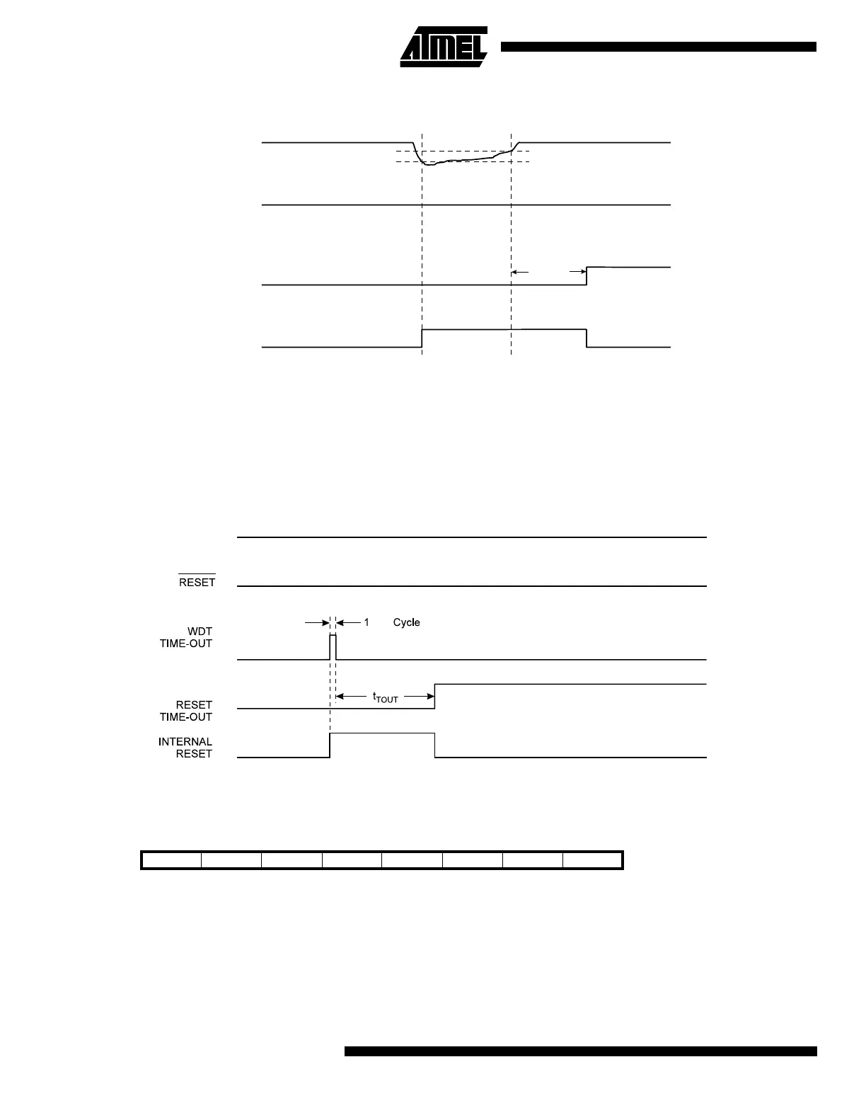
When the Watchdog times out, it will generate a short reset pulse of 1 CK cycle duration. On the falling edge of this pulse,
the delay timer starts counting the Time-out period (t
TOUT
). Refer to page 31 for details on operation of the Watchdog.
Figure 22. Watchdog Reset during Operation
MCU Status Register – MCUSR of the ATtiny10/11
The MCU Status Register provides information on which reset source caused an MCU reset.
•
Bit 7..2 - Res: Reserved Bits
These bits are reserved bits in the ATtiny10/11 and always read as zero.
•
Bit 1 - EXTRF: EXTernal Reset Flag
After a power-on reset, this bit is undefined (X). It will be set by an external reset. A watchdog reset will leave this bit
unchanged.
Bit 76543210
$34 ------EXTRFPORFMCUSR
Read/Write R R R R R R R/W R/W
Initial value 0 0 0 0 0 0 See bit description
V
CC
RESET
TIME-OUT
INTERNAL
RESET
V
BOT-
V
BOT+
t
TOUT
CK
V
CC
 Loading...


