5
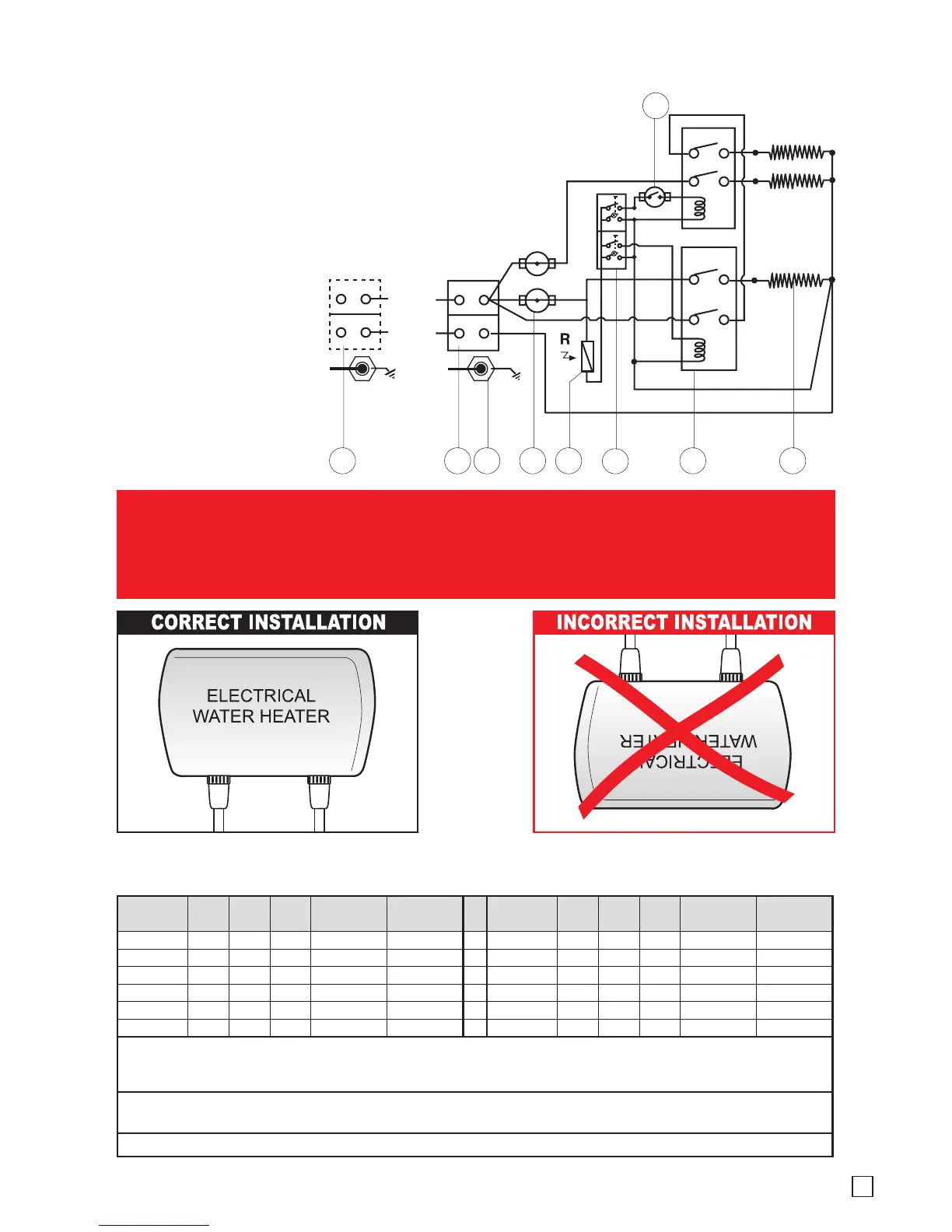
Device with 220V-240V 10.6kW- 13kW output
A. A separate electrical line is needed
as power supply for this device.
B. The device must be connected to
a separate circuit breaker.
C. The recommanded electrical cable
for feeding the device, see table I.
WARNING!
BEFORE BEGINNING ANY WORK ON THE ELECTRICAL INSTALLATION BE
SURE THAT THE CIRCUIT BREAKER IS IN THE “OFF” POSITION TO
AVOID DANGER OF ELECTRICAL SHOCK
1. Terminal block
2. Thermostat with reset
3. Thermostat
4. Switches with lights
5. Relay
6. Heating elements
7. Read sensor
8. EARTH(G) Connection in
the heating canister
Inlet and
outlet at the
bottom
INLET OUTLET
Model V ac kW AMPS
Min Field
Wire (AWG)
Min Ground
Wire (AWG)
Model V ac kW AMPS
Min Field
Wire (AWG)
Min Ground
Wire (AWG)
3.0N-110 120 3.5 30 10+ 10+ 6.0N-220 240 6.0 25 10 10
3.8N-110 120 4.4 37 6+ 10+ 6.5N-220 240 6.5 27 10 10
8.5N-220 240 8.5 35 6 10
3.5N-220 240 3.5 15 14 14 9.5N-220 240 9.5 40 6 10
3.8N-220 240 3.8 16 12 12 10.5N-220 240 10.5 44 6 10
5.5N-220 240 5.5 23 10 10 11.0N-220 240 13.0 55 4# 8#
Not specied = Cooper wire to be rate min 140 Fº
+ = Cooper wire to be rate min 167 Fº
# = Cooper wire to be rate min 194 Fº
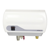
• Operating water pressure 0.5-10 bar (7-145 psi) • Water pressure operated ow switch
• Standard 1/2"Ø compression inlet connection • Top-left and right cable entry • Bottom-left water entry
UNIT DIMENSIONS: HEIGHT 7.3in WIDTH 11.8in DEPTH 3.55in
TABLE I: RECOMMENDED CABLE
L1
L2
E (G)
5 64
1
2 7
3
L
N
E (G)
8
1
 Loading...